TAGGED: ansys-mechanical, ansys-student, fluid-dynamics, fluid-flow, transient
-
-
December 30, 2020 at 1:58 am
bmarjaba
SubscriberI am simulating the resulting turbulent flow generated from injecting air at a supply (absolute) pressure of 202.65 kPa through an inlet of diameter 0.5", into a shock tube that has an initial (absolute) pressure of 101.325 kPa. The dimensions of the rectangular shock tube's cross section are 2.5"x1.5". I am only modelling a portion of the length of the shock tube, shown below. When I hit Calculate, the residuals start off below 1, and then the x, y, z equations shoot up to the order of 10's and 100's. I hope somebody can help me troubleshoot what is supposed to be a simple turbulence simulation.
My flow is compressible so I selected the density-based solver. Transient flow is selected as well. I am using the k-omega model to model the turbulence, and my solution method is implicit. I set 3 boundary conditions:
1) inlet: pressure-inlet --> Gauge pressure total pressure is set to 101325 Pa, and supersonic/initial gauge pressure is set to 0 (i also tried different pressures here)
2) left and right planes indicated in the diagram: both set as pressure-outlet --> gauge pressure is set to 0 as that is the gauge pressure in my shock tube at those two locations
Are the boundary conditions correctly set? Is anything missing?
In the solution initialization, I am computing from inlet, where the Y-velocity is automatically set to -329 m/s2.
The below attached images are of the shock tube, the fluid domain (air) that I am modelling, the mesh, and the set boundary conditions in FLUENT.
December 30, 2020 at 2:23 pmKonstantin
Ansys Employeehow's time step selected?nDecember 30, 2020 at 3:22 pmbmarjaba
SubscriberI tried:n10 time steps with step size of 0.1 secondsn20 time steps with step size 0.05 secondsnnDecember 30, 2020 at 3:26 pmKonstantin
Ansys Employeewhy these time steps? what is the flow convective CFL (hint: it should be ~ 1)nDecember 30, 2020 at 4:02 pmbmarjaba
SubscriberMy Courant number is set at 5. Why should it be 1? I'll try 1.nI chose those time steps because I want to simulate 1 second of injection - as a start at least. nDecember 30, 2020 at 4:12 pmKonstantin
Ansys EmployeeConvective CFL has nothing to do with the CFL defined in the solution controls. This CFL controls dual time stepping. Convective CFL ~ U dt/dx. What it is in you case? Basically, you should not drive the flow faster than 1 cell per time step, especially if it has sharp gradients.nDecember 30, 2020 at 4:27 pmbmarjaba
Subscriberoh. so i'll keep the Courant number in the solution controls as 5, and i'll set the convective CFL to <=1. where can i find the convective CFL though?nDecember 30, 2020 at 6:53 pmbmarjaba
Subscriberoh you mean i should choose a time step (dt) that will give me a CFL = 1 according to the equation U dt/dx. I get it. For the velocity it initializes from (322 m/s), the required time step that gives me a CFL of 1 is 4.86e-5 s. So in order to simulate 1 second of flow, I need 20,573 time steps? That's huge.nDecember 30, 2020 at 7:10 pmKonstantin
Ansys Employeefor reporting convective CFL, you can temporarily switch to the pressure-based solver which has convective CFL under velocity. No need to run the solution in pressure-based to inspect the CFL.nRequirement to maintain convective CFL ~ 1 (and acoustic CFL if you are interested in acoustics) is pretty much universal across CFD solvers. The implicit density-based formulation allows you to run with larger CFLs but at a cost of loosing transient information due to numerical dissipation and potentially arriving to a wrong answer. Very large CFLs can also lead to stability problems, as you are observing.nBut as long as you understand the trade off between larger time step and accuracy/fidelity of the solution, you ca try larger steps.nDecember 30, 2020 at 11:08 pmbmarjaba
Subscriberokay thank you! im running the simulation explicitly with a courant number set at 1. im trying to add a plot in the monitor for courant number in order to monitor it and make sure it doesn't go above 1, but i can't find it anywhere when creating a report definition. I read somewhere that im supposed to find it under velocity when creating a volume monitor. Any idea how to add that to my monitor? I'm using ANSYS Fluent 2020.nDecember 31, 2020 at 2:33 pmKonstantin
Ansys EmployeeAs per my previous note, convective CFL is available as a post-processing quantity in the pressure-based solver, but not in the density-based, You can construct an expression or custom field function using available post-processing quantities: velocity magnitude and (cell volume)^(1/3) and monitor it. nJanuary 21, 2021 at 11:58 pmbmarjaba
SubscriberHello. So I ran this simulation using a pressure based solver, since my flow is subsonic and is not THAT compressible. I first ran it steady-state for 1000 iterations and used the solution to initialize the transient sim. The simulation ran very smoothly with no problems at all, the residuals retained a consistent typical zig-zag form through, and was converging with every time-step. Results looked logical, net mass flow rate was almost 0 through all boundaries, etc.nMy settings for the steady-state sim are: pressure-based solver, coupled scheme with pseudo transient activated and a timescale factor of 0.1 (that was the only one that got my solution to start converging).nMy settings for the transient model are: Pressure-based solver, PISO scheme, Adaptive time-stepping, CFL-based, Courant number = 0.5. Those settings ran perfectly for the simulation done before I added the pipe inlet.nI then added a pipe to the inlet because the previous simulation did not account for the sudden expansion that occurs when the flow leaves the pipe into the shock tube. I also ran the steady state solution first, but the residuals were slightly different than the first sim, in that the continuity residual did not decrease with the others, but was nevertheless stable:n I used the SS solution to initialize the transient sim, the zig-zag form varied slightly throughout, the solution was converging for every time-step, until it started diverging - then crashed. From the moment i started the transient simulation, the net mass flow rate kept decreasing below 0 until it crashed. Below are snap shots of the residuals before the solution began to diverge, and after it diverged.n
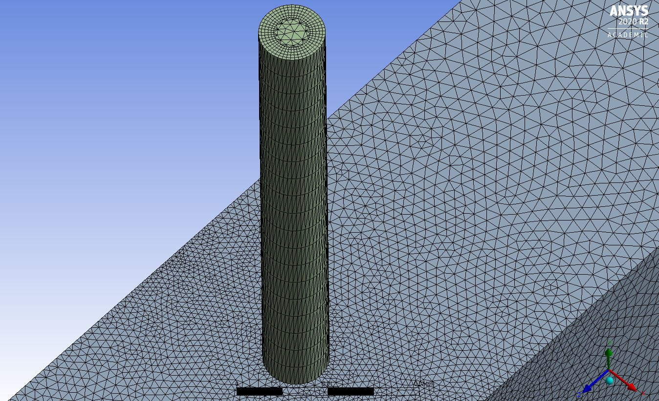
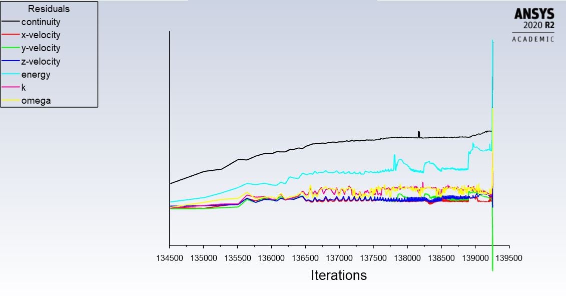 Here is part of the error message I got:nReversed flow on 329 faces (99.7% area) of pressure-inlet 6.nStabilizing k to enhance linear solver robustness.nNegative k in 54992 cells after linear solve.nStabilizing temperature to enhance linear solver robustness.nStabilizing temperature using GMRES to enhance linear solver robustness.nDivergence detected in AMG solver: temperaturen absolute pressure limited to 5.000000e+10 in 39988 cells on zone 4 n turbulent viscosity limited to viscosity ratio of 1.000000e+05 in 479327 cells nDivergence detected in AMG solver: temperaturen Reversed flow on 3176 faces (83.4% area) of pressure-outlet 7.n Reversed flow on 124 faces (1.7% area) of pressure-outlet 8.nDivergence detected in AMG solver: temperaturenDivergence detected in AMG solver: temperaturenError at host: floating point exceptionnError at Node 1: floating point exceptionnError at Node 0: floating point exceptionnError at Node 2: floating point exceptionnError at Node 3: floating point exceptionn===============Message from the Cortex Process================================nCompute processes interrupted. Processing can be resumed.n==============================================================================nError: floating point exceptionnError Object: #fn------------------------------------------------------------------------------------------------------nDo you think the mesh is the problem? That's the only thing that changed since I added the pipe to the inlet. Here are my mesh metrics, and some snaps of my mesh.northogonal quality:nmax: 4.2318e-002nmin: 0.99817naverage: 0.72103nstandard deviation: 0.186nnskewness:nmax: 4.5386e-005nmin: 0.95741naverage: 0.27731nstandard deviation: 0.18758nnaspect ratio:nmax: 1.1601nmin: 147.36naverage: 4.4613nstandard deviation: 3.0285nnelement quality:nmax: 1.4197e-003nmin: 0.99998naverage: 0.5242nstandard deviation: 0.25719n
 n
January 22, 2021 at 1:56 pm
n
January 22, 2021 at 1:56 pmKarthik Remella
AdministratorHello,nFirstly, this is not a good mesh to run your simulations on. Your mesh quality is poor and needs improvement.nSecondly, what is your inlet condition? nAlso, what is the Mach Number at the nozzle exit? I ask this question because you are talking about the propagation of shock. nWhat material properties are you using? Specifically, density.nKarthikJanuary 22, 2021 at 2:30 pmKonstantin
Ansys EmployeeTo add to Karthik's comments, I am sure you did due diligence and checked the steady-state simulation to confirm the flow developed as expected. Mesh min ortho quality is low but not too awful. Before investing into redoing the mesh, can you confirm what is happening before the divergence? E. g. save contours of the flow field (velocity, pressure, Mach) on the center plane through the domain (YZ plane) every few steps to identify what happens when the divergence occurs. This will give some pointers as to where the problem maybe coming from. Also, monitor your time step to see if it changes suddenly at the time of the crash.nJanuary 22, 2021 at 11:05 pmbmarjaba
SubscriberHey guys. Thank you for your replies.n1) Yeah I'm not happy with the cylindrical pipe's mesh at all, but I've been having difficulty generating a good one. The cells on the outer surface look very skewed to me, but if my mesh metrics are within the required ranges as specified by the tutorials, then what exactly defines my mesh as good enough or bad enough? What guidelines do you recommend I follow in order to generate a good enough mesh for this simulation? Is the rectangular shock tube's mesh bad too or is it just the pipe? n2) My boundary conditions are: ninlet is set as pressure-inlet --> Gauge total pressure is set to 101325 Pa, and supersonic/initial gauge pressure is set to 0 (i'm going to set this to 5731 Pa gauge because that is the pressure when the flow reaches M=1, is that what this parameter is defined as?) nleft and right planes are both set as pressure-outlet --> gauge pressure is set to 0 as that is the gauge pressure in my shock tube at those two locationsn3) My maximum Mach number at the pipe exit according to the generated contours at around 94,700 iterations of the transient sim is around 1.08, so there should be shocks in my flow. i miscalculated that earlier. should i switch to a density-based solver in this case? if so, implicit or explicit?n4) I'm using air as a compressible ideal gas, with density 1.225 kg/m3 at standard conditions.n5) I'm re-running the simulation now to capture contours at different stages as advised. I'll have them uploaded by tomorrow, as well as the variation in time steps. When do I know when to stop increasing the Courant number? At 0.5, the time step remains constant at 1e-8, and at 0.55, it also remains constant at 1e-5. But when I set it at 0.6, the time step starts to increase. Is this a sign that I should leave it at 0.55?nJanuary 23, 2021 at 8:36 pmbmarjaba
SubscriberBelow are contours of Mach Number, Velocity Magnitude, and Static Pressure t=0.002079 seconds (before it crashed), and at t=0.0021082 seconds (after it crashed). I also monitored the inlet pressure, the mass flow rate, and the time step.n1) The time step remained constant at 1e-8 for the entire time. It did not change even after it crashed. I had the courant number set to 0.55. I tried increasing it to 0.6 and 0.7 at times and the time step started increasing, then i returned it to 0.55. But at a courant of 0.5 and 0.55, it was constant throughout at 1e-8.n2) The average weighted inlet pressure fluctuated around 6.816-6.82 kPa, before it shot straight up to huge numbers and fluctuating after 0.0021077 seconds, until it crashed. I posted screenshots of the plots of both phases.n
 n3) The mass flow rate was steadily decreasing below 0.0001 before it crashed. Plots of both phases are shown below.n
 4) Mach Numbers before and aftern
 n
n 5) Velocity before and aftern
 5) Static Pressure before and aftern
 nn
January 25, 2021 at 2:52 pm
nn
January 25, 2021 at 2:52 pmKonstantin
Ansys Employeesince the flow becomes mildly supersonic and the mesh quality is poor, I'd recommend the pressure-based coupled solver (use Coupled option in p-v coupling). It can hold together well into the supersonic regime, no need to switch to the dbns. If there are still problems, the revisiting the mesh would be a good idea.nJanuary 27, 2021 at 3:27 pmbmarjaba
Subscriberokay i'll do that. are there certain guidelines you recommend i follow in order to achieve a good quality mesh? and is it the pipe only that's bad quality? or is it the shock tube as well? i have a bias near the shock tube walls and near the vicinity of the jet.nJanuary 27, 2021 at 3:34 pmKonstantin
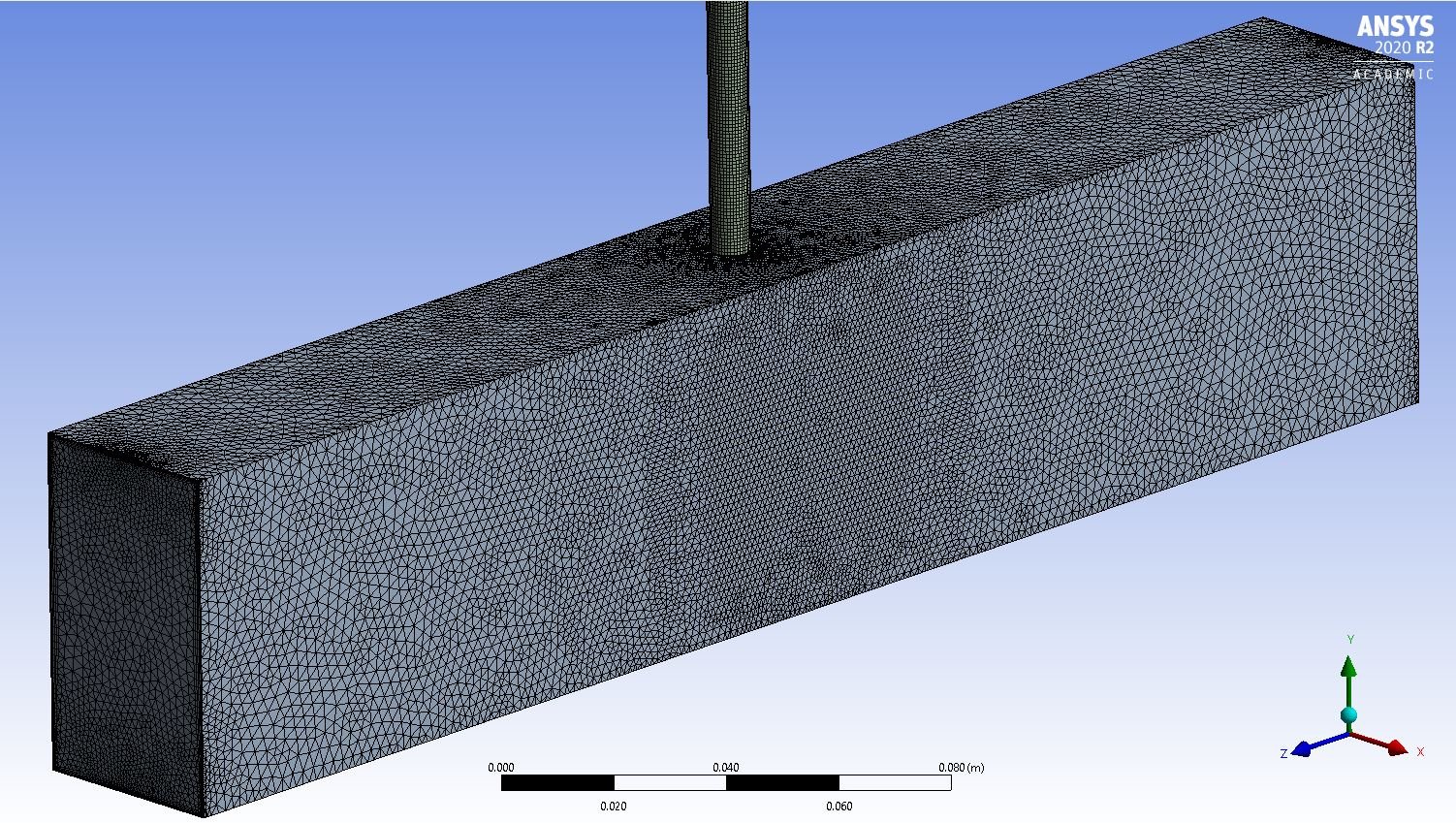
Ansys EmployeeI would sweep-mesh the pipe so it would have good quality hex mesh, and then tet mesh the rest. It's hard to say just by looking at the surface mesh where bad-quality cells are, but definitely the pipe has highly skewed elements. So define the sweep method for the pipe volume, mesh it fist and then mesh the shock tube.nFebruary 4, 2021 at 9:18 pmbmarjaba
SubscriberSo i fixed the mesh using your suggested method, and it looks much better. Below are the mesh metrics and screenshots of the mesh:northogonal quality:nmax: 0.10314nmin: 0.9997naverage: 0.74944nstandard deviation: 0.14951nnskewness:nmax: 4.4457e-009nmin: 0.89686naverage: 0.2491nstandard deviation: 0.15097nnelemental quality:nmax: 9.3866e-002nmin: 0.99997naverage: 0.58812nstandard deviation: 0.2668nnAspect ratio:nmax: 1.1595nmin: 16.521naverage: 3.9131nstandard deviation: 2.4327n
 nHere are screenshots of the residuals and contours for the steady state solution, they seem logical and fine to me:n
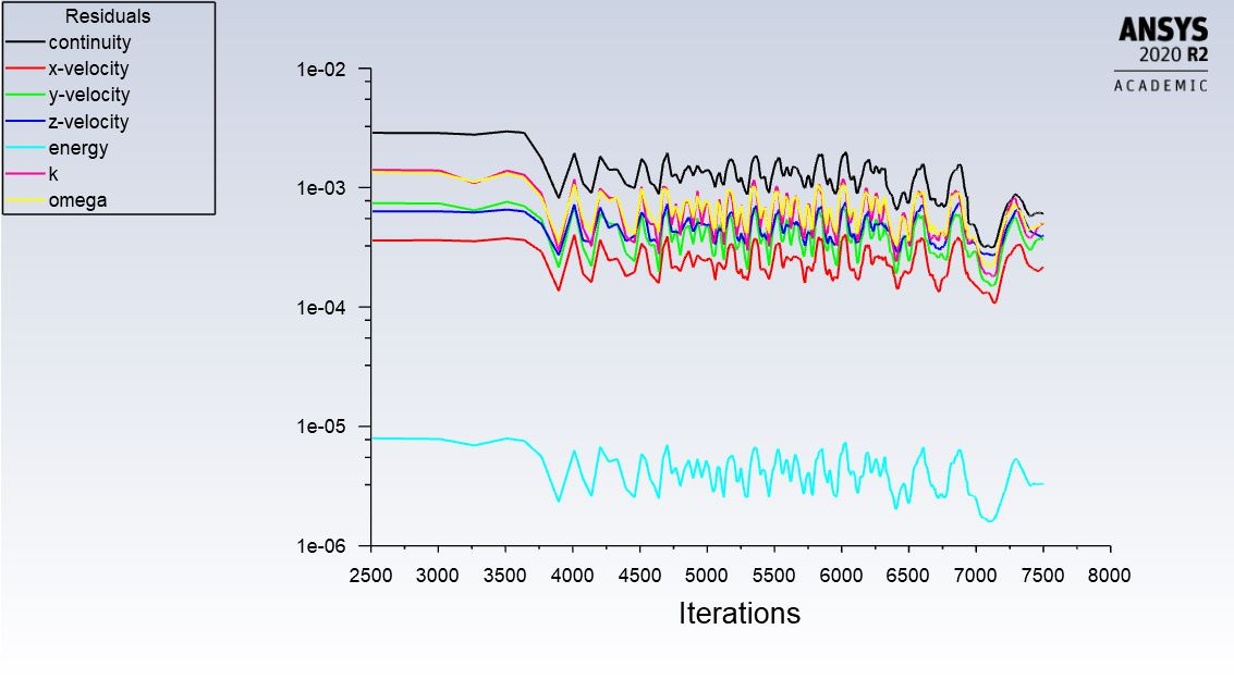


 nAnd here are the residuals and contours for the transient solution. I used coupled scheme here, and i also tried the piso but i wasnt able to get proper residuals. the contours are very much similar to the steady state because (i assume) i used the steady state solution to initialize my transient one, and the time step that was generated using the adaptive method was 1e-8, hence there wasnt much advancement in the flow time since initialization. but the problem is the residuals, and the net mass flow rate at the inlet deviated heavily from 0.n
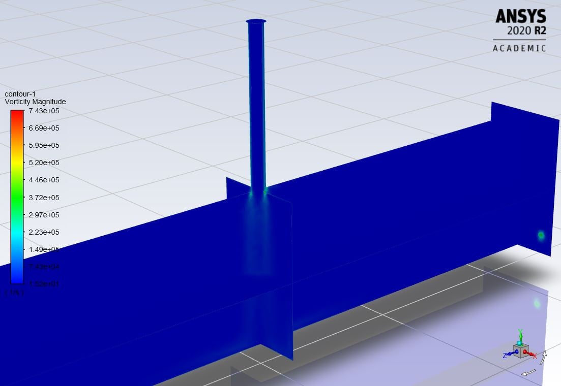
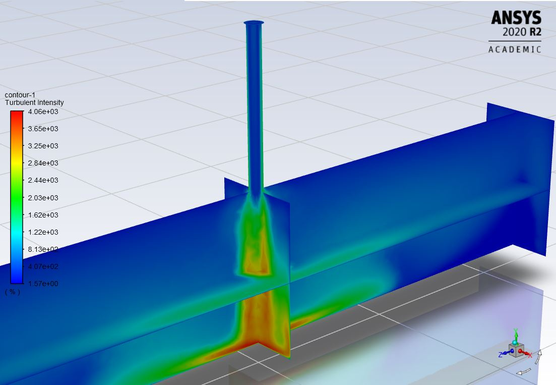

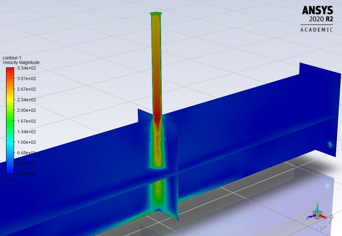
 n
February 5, 2021 at 3:25 pm
n
February 5, 2021 at 3:25 pmKonstantin
Ansys Employeeactually, looks pretty good. Residuals in transient have some different meaning then in steady-state. All you should be looking is residuals go done ~ 1e-03 within each step. Keep in mind that once you switch to transient, you start recovering transient artifacts (propagating waves) which otherwise don't exist in steady-state. Since this is a closed domain, waves inevitable reflect off the walls, maybe travel upstream along the tube. They should eventually dissipate, My suggestion is to switch to a constant time step, use a larger step at flow CFL ~ 1, and keep coupled. This should allow you to flash out initial transient faster.nFebruary 8, 2021 at 3:59 pmbmarjaba
Subscriber1- yeah but the residuals for the transient case did not go down 1e-03 within each step (specifically continuity), that is what made me doubt that it was going well.n2- i would just like to confirm how to calculate the time step at CFL~1? is it using CFL=U dt/dx? at CF1~1, this means dt = dx/U. but what is the dx to be used here? is it the minimum edge length, minimum characteristic length, or average characteristic length? they largely differ from each other. n n
February 8, 2021 at 4:43 pm
n
February 8, 2021 at 4:43 pmRob
Forum ModeratorThat means something is changing faster than the time step will pick up. Drop the time step and see what happens. The CLF you want to calculate is (approximately) cell length / velocity. I'd aim for CFL = 1/10 to allow for not knowing the cell size or velocity everywhere as you can always slowly increase the time step once the solution is running. nFebruary 9, 2021 at 4:35 pmbmarjaba
Subscriberi see, okay. i'll try that as well. nso i ran it with the following settings yesterday: Coupled scheme, Flow Courant Number =1 in solution controls, fixed time step method, time step = 1e-06. nthe residuals looked good to me, where each equation dropped a minimum of 1e-03 for each time step and the solution was converging, and i ran it over night. i came back today morning and found that it has crashed. the contours and the residuals look good to me before and after it crashed, i monitored the net mass flow rate throughout and it hovered around a number really close to 0 even after it crashed. this was the error message:nReversed flow on 1384 faces (31.9% area) of pressure-outlet 8.n!44051 solution is convergedn 44051 5.5133e-08 4.5500e-08 6.2184e-08 1.0478e-07 2.7427e-10 5.8664e-10 7.6547e-10 0:00:11 6n step flow-time mass-flow-ra flow-timen 2662 2.6620e-03 1.0639e-04 2.6620e-03nFlow time = 0.002662s, time step = 2662nRegistering ReportDefFiles, (C:\Users\bmarjaba\Documents\Turbulent Jet_files\dp0\FFF-1\Fluent\.\report-file-0.out C:\Users\bmarjaba\Documents\Turbulent Jet_files\dp0\FFF-1\Fluent\.\mass-flow-rate-rfile.out C:\Users\bmarjaba\Documents\Turbulent Jet_files\dp0\FFF-1\Fluent\.\inlet-pressure-rfile.out)nCan't figure which cell particle is going to -- ABORTnCannot find intersecting face for particle 2416 step 193 -- ABORT at (2.889059e-02 6.984949e-02 1.537980e-01) in cell 114868 , t-id 4, next_pos = (2.889059e-02 6.984949e-02 1.537980e-01)nCan't figure which cell particle is going to -- ABORTnCannot find intersecting face for particle 2306 step 164 -- ABORT at (2.888347e-02 6.984949e-02 1.537913e-01) in cell 114868 , t-id 4, next_pos = (2.888347e-02 6.984949e-02 1.537913e-01)n........n........n........nCan't figure which cell particle is going to -- ABORTnCannot find intersecting face for particle 5588 step 192 -- ABORT at (2.663768e-02 6.984948e-02 1.560050e-01) in cell 114729 , t-id 4, next_pos = (2.663768e-02 6.984948e-02 1.560050e-01)nCan't figure which cell particle is going to -- ABORTnCannot find intersecting face for particle 6337 step 399 -- ABORT at (2.344654e-02 6.984946e-02 1.490714e-01) in cell 119545 , t-id 4, next_pos = (2.344654e-02 6.984946e-02 1.490714e-01)nnumber tracked = 60687, escaped = 24068, aborted = 71, incomplete = 36606nWriting data to C:\Users\bmarjaba\Documents\Turbulent Jet_files\dp0\FFF-1\Fluent\FFF-1.ip ...ntx-coordnty-coordntz-coordntpressurentx-velocitynty-velocityntz-velocitynttemperaturentkntomeganDone.nnCalculation complete.February 9, 2021 at 4:59 pmKonstantin
Ansys Employeethe ABORT message comes from the DPM part and it can be a factor of your DPM settings (injections etc). As for the mass flow rate, where do you measure it? Inlet, outlet or somewhere else?nFebruary 9, 2021 at 7:18 pmbmarjaba
Subscriberany idea on what to do with my DPM settings?ni'm monitoring the net mass flow rate across all boundaries (inlet + outlet 1 + outlet 2), should be almost 0 as mass is conserved.nFebruary 9, 2021 at 8:47 pmKonstantin
Ansys Employeefor DPM - can you share screenshots of your DPM settings? You don't have any mesh interfaces of moving parts, right?nMass is conserved only in a transient fashion, i. e. m_in is not necessarily equal to m_out unless the transient term is zero.nFebruary 9, 2021 at 10:20 pmFebruary 11, 2021 at 7:19 pmKonstantin
Ansys EmployeeI don't see injections defined, but you are injecting particles:nnumber tracked = 60687, escaped = 24068, aborted = 71, incomplete = 36606nwhere are they coming from?nFebruary 12, 2021 at 7:39 pmbmarjaba
Subscriberim simulating the injection of air (through the pipe inlet at the top) at a supply pressure of 200 kPa into a shock tube of pressure 100 kPa. setting the boundary conditions at the inlet at 200 kPa and pressure far field in the tube at 100 kPa causes a pressure gradient and therefore leads to injection, no? i honestly don't know where else those particles could come from.nFebruary 15, 2021 at 11:47 amRob
Forum ModeratorParticles don't just appear, so there must be something set in the solver. However, gas into gas doesn't require the DPM model so i don't know why you've turned it on either. nFebruary 24, 2021 at 12:16 ambmarjaba
Subscriberyeah I don't know why it was on either, I never touched that setting. I disabled Unsteady Particle Tracking and it ran without errors. Thank you for your help gentlemen.nI am planning to run more simulations but with different pressure ratios (only for up to 2 seconds transient simulation). The one described in this thread has a pressure ratio of 2 (Psupply/Ptube = 200 kPa / 100 kPa). Other pressure ratios I would like to try range from 4 to 50. This will result in a higher Mach number, more turbulence and more shock waves generated. Do you suggest I keep the same settings as I did for a PR of 2? Do I keep a pressure-based solver or do i switch to a density-based? Do I keep it as coupled? what do I do with the Flow Courant number, time step, etc.?nThanksnViewing 31 reply threads- The topic ‘Simulation of a jet of air into a shock tube’ is closed to new replies.
Innovation SpaceTrending discussionsTop Contributors-
4989
-
1670
-
1386
-
1243
-
1021
Top Rated Tags© 2026 Copyright ANSYS, Inc. All rights reserved.
Ansys does not support the usage of unauthorized Ansys software. Please visit www.ansys.com to obtain an official distribution.
-


