

TAGGED: airfoil, drag-force, error-in-results, lift
-
-
December 27, 2020 at 11:51 pm
AlexT
SubscriberHi everyone, any help and opinion is appreciated. I am simulating airfoil profils (2D) in fluent 2020 R2 academic. In every simulation results are unrealistic. I have tried unsuccessfully several times to understand what is going wrong. I am a beginner with fluent, so I am definitely doing something wrong and I think you can help me. I emphasize that the mistake is always the same.
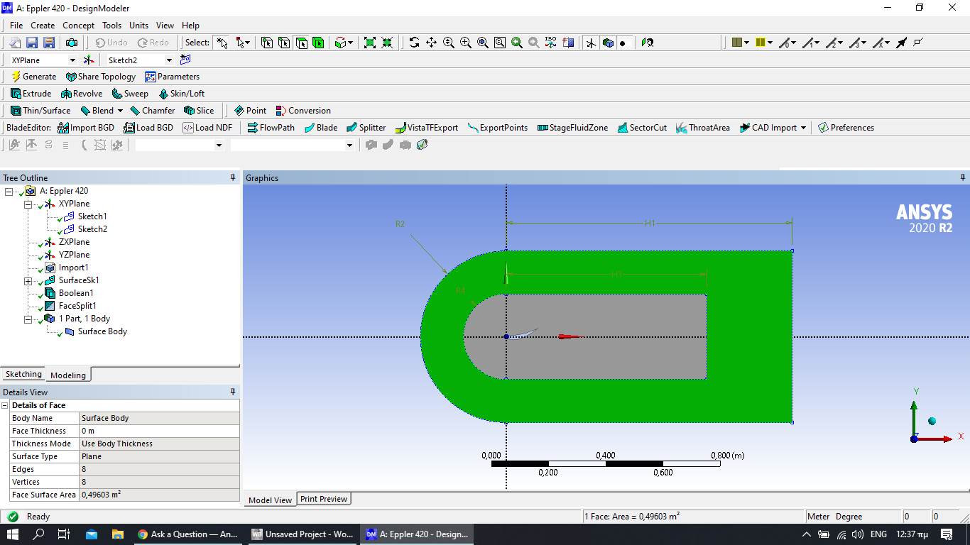
Just an example, trying to have some results for the Eppler 420 airfoil.
Airfoil Eppler 420
Chord 140mm
AOA 15 deg
Importing .IGS file from Solidworks
K-ω SST (but I have also tested several models)
Inlet Velocity 20 m/s
here follows the whole process I performed:
December 28, 2020 at 1:38 ampeteroznewman
SubscriberI recommend deleting the All Triangles Method mesh control you are using.nA major defect in the model is the mesh has no inflation layer. Below is an example of a mesh with an inflation layer on the airfoil boundary edge.n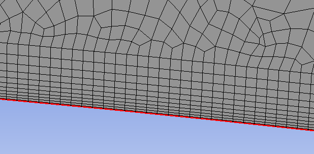 Use an Inflation mesh control. This example shows a 1 mm First Layer Height. Don't use 1 mm. n
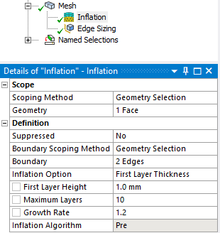 Read this discussion to determine the correct First Layer Height for your model.n/forum/discussion/1522/near-wall-treatmentn
December 29, 2020 at 8:43 pmSubscriberArraythank you for your prompt reply! nI changed the triangle method I used and added an inflation layer on the airfoil boundary edge. I had better results but still unrealistic - really big coefficients. I guess I have to try hard to find the ideal mesh and setup. nΤhe strange thing is that in some tutorials users relatively easy and quick approach a logical if not ideal solution. nDecember 29, 2020 at 9:17 pmSubscriberI assume you used Inlet Velocity components and did not leave it as the default of Normal to Surface. You didn't show that input so is it possible you forgot to change the default?nDecember 29, 2020 at 10:09 pmSubscriberYes right. I did not make any change to this field. So it is the default.nI only set the inlet velocity as 20 m/s. nDecember 29, 2020 at 10:18 pmSubscribernShould I change the default ?n(I hope I understood correctly about the input you mentioned):n
Read this discussion to determine the correct First Layer Height for your model.n/forum/discussion/1522/near-wall-treatmentn
December 29, 2020 at 8:43 pmSubscriberArraythank you for your prompt reply! nI changed the triangle method I used and added an inflation layer on the airfoil boundary edge. I had better results but still unrealistic - really big coefficients. I guess I have to try hard to find the ideal mesh and setup. nΤhe strange thing is that in some tutorials users relatively easy and quick approach a logical if not ideal solution. nDecember 29, 2020 at 9:17 pmSubscriberI assume you used Inlet Velocity components and did not leave it as the default of Normal to Surface. You didn't show that input so is it possible you forgot to change the default?nDecember 29, 2020 at 10:09 pmSubscriberYes right. I did not make any change to this field. So it is the default.nI only set the inlet velocity as 20 m/s. nDecember 29, 2020 at 10:18 pmSubscribernShould I change the default ?n(I hope I understood correctly about the input you mentioned):n n
December 29, 2020 at 11:14 pmSubscribernYes, this is one reason why your lift and drag coefficients are way off.nThe Velocity Specification Method is not correct. The air is coming in normal to the semi-circle, that is directed toward the center of the circle where it collides with the wing.nYou want Components. You want the air coming in parallel to the X axis in a nice smooth air stream.nPut 20 m/s in the X component and 0 m/s in the Y component.nViewing 6 reply threads
n
December 29, 2020 at 11:14 pmSubscribernYes, this is one reason why your lift and drag coefficients are way off.nThe Velocity Specification Method is not correct. The air is coming in normal to the semi-circle, that is directed toward the center of the circle where it collides with the wing.nYou want Components. You want the air coming in parallel to the X axis in a nice smooth air stream.nPut 20 m/s in the X component and 0 m/s in the Y component.nViewing 6 reply threads- The topic ‘Unrealistic results – excessively high lift force and drag (cd) values in a 2D airfoil analysis’ is closed to new replies.
Ansys Innovation Space Trending discussions
 Top Contributors
-
peteroznewman
 3637
3637 -
scabo
 1313
1313 -
Dennis Chen
 1142
1142 -
javat33489
 1069
1069 -
Shyam Prasad V Atri
1013
Top Rated Tags
© 2025 Copyright ANSYS, Inc. All rights reserved.
Ansys does not support the usage of unauthorized Ansys software. Please visit www.ansys.com to obtain an official distribution.
-


The Ansys Learning Forum is a public forum. You are prohibited from providing (i) information that is confidential to You, your employer, or any third party, (ii) Personal Data or individually identifiable health information, (iii) any information that is U.S. Government Classified, Controlled Unclassified Information, International Traffic in Arms Regulators (ITAR) or Export Administration Regulators (EAR) controlled or otherwise have been determined by the United States Government or by a foreign government to require protection against unauthorized disclosure for reasons of national security, or (iv) topics or information restricted by the People's Republic of China data protection and privacy laws.


