
-
-
December 23, 2020 at 11:58 am
Tef
SubscriberHey Everyone,
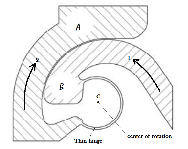
I am doing a static structural analysis on one structure which is constructed by hinges (as you see the attached picture). The overall structure works by applying an input displacement. The hinges have rotational motion and I want to fix the center of rotation at C. So, how can i fix the COR at point C? unless during rotation, the thin hinge translates and the COR drifts.
Thank you in advance!
With best regards,
Teferi
December 24, 2020 at 3:47 ampeteroznewman
SubscriberArraynIf I was asked to study the design of this hinge, I would pick one side as fixed and the other side as moving, to simplify the analysis. For example, let's assume the large flat top on A is given a Fixed Support and B is the moving side of the hinge.nI see coincident cylindrical faces between A and B where I would put Frictional Contact. nThe rightmost straight edge on B can be a face where forces and moments are applied. For each combination of forces and moments, the hinge will react according to the stiffness of the material in the hinge and the contact forces between the two parts.nSome values of forces and moments will work the hinge in the intended way, and produce a rotation about C, other values of forces and moments will pull the hinge apart and will not provide a rotation about C. My study would map out the set of forces and moments for which the hinge works by rotating about C and map the boundary on the set of forces and moments where the hinge falls apart and rotation drifts away from C.nIt's not clear from your question, but you seem to ask how to constrain the two parts to force them to rotate about C even if the hinge would have come apart under some applied forces and moments, you just want the two parts to rotate about C even though they would not have in reality. Am I understanding you correctly? If that is what you want, then you simply select a face on A and another face on B and create a Revolute Joint. Put the origin of the Joint coordinate system at C and have the Z axis point out of the page, then the two parts will be forced to rotate about C. In this scenario, it will simplify the model if you cut out the thin strip between A and B.nDecember 24, 2020 at 6:25 pmSubscriberThank you very much Sir!nActually you are right, only one part rotates and the other part will be fixed. I was trying to do by replacing the hinges by revolute joint but i didn't have any idea about Body-body and Body-ground concepts.nTo make it clear, the total structure is constructed from 6 hinges. I can't post the overall structure here but let me attach one diagram. Hopefully it will clarify the mechanism. And, if you can, would you mind telling me the procedures which i have to do in Ansys workbench by replacing the hinges with revolute joints for the attached structure.n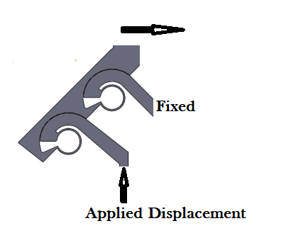 n
December 24, 2020 at 7:41 pmSubscribernFirst cut the thin hinge section away on each location, then you will have 3 bodies instead of 1 body.nFor the first Revolute, select a cylindrical face on the Fixed body and a cylindrical face on the link body.nFor the second Revolute, pick the two cylindrical faces on the link and the input body.nThe small face that has the Applied Displacement should have a Remote Displacement created. If that figure is in the XY plane, then you want to assign the displacement to the Y component, but you will also have to assign a 0 to the X component, since this mechanism has 2 DOF and without the X = 0 constraint, the remote point could slide sideways.nUnder Analysis Settings, make sure to turn on Large Deflection if you are running a Static Structural. If you did this in Rigid Dynamics, then you would not need to do that.nDecember 25, 2020 at 1:59 pmSubscriberOk, many thanks Sir!nThe model should be like this one right? then the thin hinges will be replaced by the revolute joint in ansys.n
n
December 24, 2020 at 7:41 pmSubscribernFirst cut the thin hinge section away on each location, then you will have 3 bodies instead of 1 body.nFor the first Revolute, select a cylindrical face on the Fixed body and a cylindrical face on the link body.nFor the second Revolute, pick the two cylindrical faces on the link and the input body.nThe small face that has the Applied Displacement should have a Remote Displacement created. If that figure is in the XY plane, then you want to assign the displacement to the Y component, but you will also have to assign a 0 to the X component, since this mechanism has 2 DOF and without the X = 0 constraint, the remote point could slide sideways.nUnder Analysis Settings, make sure to turn on Large Deflection if you are running a Static Structural. If you did this in Rigid Dynamics, then you would not need to do that.nDecember 25, 2020 at 1:59 pmSubscriberOk, many thanks Sir!nThe model should be like this one right? then the thin hinges will be replaced by the revolute joint in ansys.n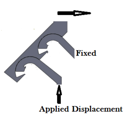 And, what is the difference between using static structural and using rigid dynamics in this case Sir?nThank you in advance!nn
December 25, 2020 at 7:19 pmSubscribernYes, in Mechanical, when you pick a cylindrical face to define the joint, it should automatically snap the joint coordinate system origin to the center of the cylinder with the Z axis aligned to the cylindrical axis. The coordinate system will display when you click on the Joint in the outline.nIn Static Structural, it will mesh the three bodies and take longer to compute the motion due to the applied displacement, and the 1 second end time is really just a counter to keep track of the fraction of applied displacement that has been applied.nIn Rigid Dynamics, it will take less time to compute the motion, but it is in terms of dynamics, which means the velocity depends on the end time, but 1 second is reasonable for the small displacements you are considering.nDecember 25, 2020 at 7:34 pmSubscriberOk, I see. Many thanks for all your suggestions and clarifications Sir. nViewing 6 reply threads
And, what is the difference between using static structural and using rigid dynamics in this case Sir?nThank you in advance!nn
December 25, 2020 at 7:19 pmSubscribernYes, in Mechanical, when you pick a cylindrical face to define the joint, it should automatically snap the joint coordinate system origin to the center of the cylinder with the Z axis aligned to the cylindrical axis. The coordinate system will display when you click on the Joint in the outline.nIn Static Structural, it will mesh the three bodies and take longer to compute the motion due to the applied displacement, and the 1 second end time is really just a counter to keep track of the fraction of applied displacement that has been applied.nIn Rigid Dynamics, it will take less time to compute the motion, but it is in terms of dynamics, which means the velocity depends on the end time, but 1 second is reasonable for the small displacements you are considering.nDecember 25, 2020 at 7:34 pmSubscriberOk, I see. Many thanks for all your suggestions and clarifications Sir. nViewing 6 reply threads- The topic ‘How to fix the center of rotation in static structural analysis in ansys?’ is closed to new replies.
Innovation Space Trending discussions
 Top Contributors
-
peteroznewman
 6309
6309 -
scabo
 1906
1906 -
Dennis Chen
 1457
1457 -
javat33489
 1308
1308 -
Shyam Prasad V Atri
1022
Top Rated Tags
© 2026 Copyright ANSYS, Inc. All rights reserved.
Ansys does not support the usage of unauthorized Ansys software. Please visit www.ansys.com to obtain an official distribution.
-


The Ansys Learning Forum is a public forum. You are prohibited from providing (i) information that is confidential to You, your employer, or any third party, (ii) Personal Data or individually identifiable health information, (iii) any information that is U.S. Government Classified, Controlled Unclassified Information, International Traffic in Arms Regulators (ITAR) or Export Administration Regulators (EAR) controlled or otherwise have been determined by the United States Government or by a foreign government to require protection against unauthorized disclosure for reasons of national security, or (iv) topics or information restricted by the People's Republic of China data protection and privacy laws.
