TAGGED: pivot, pivot-warning
-
-
December 23, 2020 at 3:51 am
-
December 23, 2020 at 5:51 am
BenjaminStarling
SubscriberSplit your model in half and use a Symmetry Boundary Condition. Otherwise restrain one (ore a few) nodes on the crosshead in the X direction.n -
December 23, 2020 at 6:24 am
jinglun
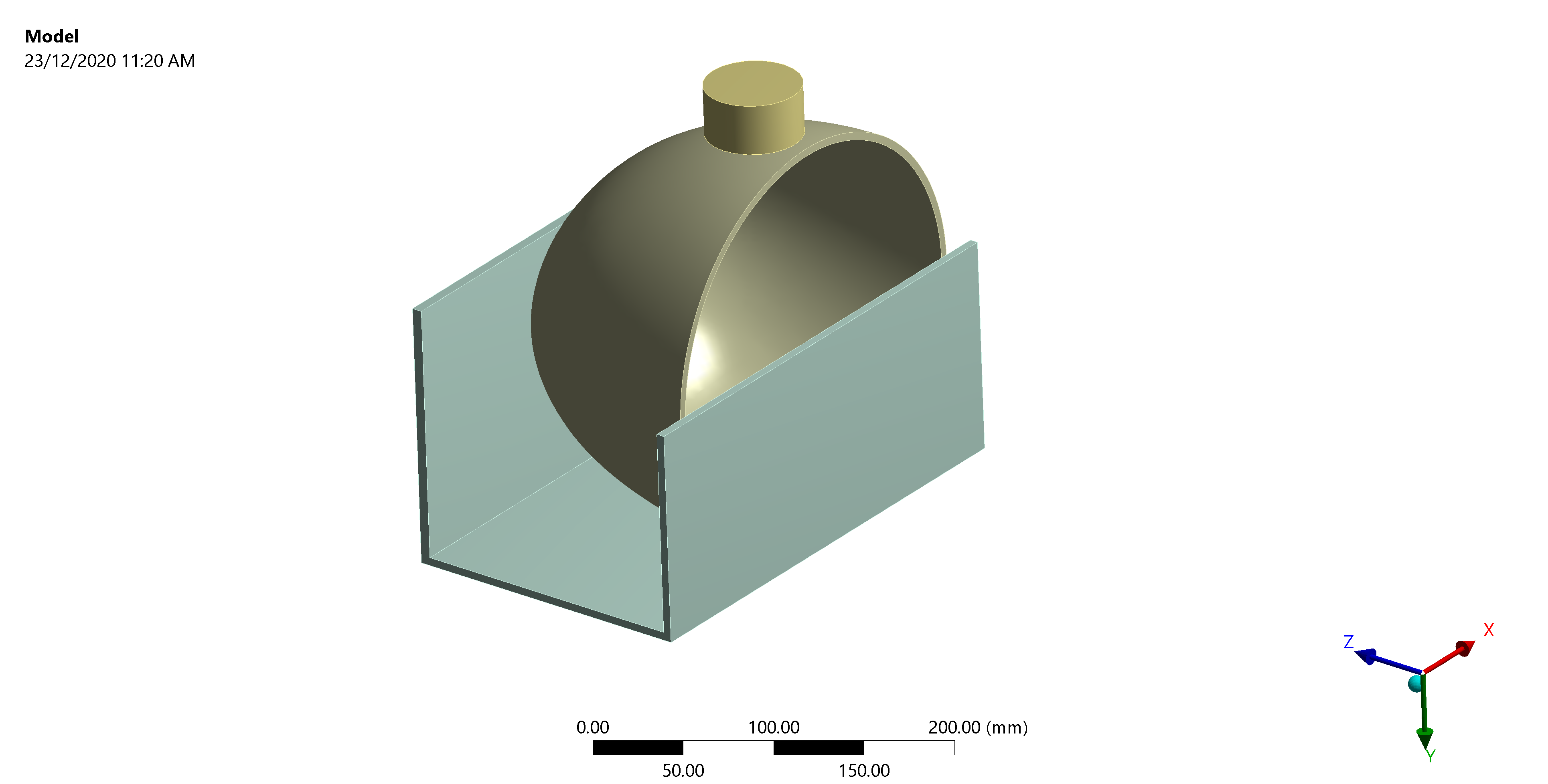
Subscriberthanks for your suggestion! Sorry but I forgot to mention that the hemisphere is not symmetrical. So symmetry would not be applicable in my case.Other than that, did you mean restrain the nodes on the hemisphere, instead of the crosshead?n -
December 23, 2020 at 7:06 am
BenjaminStarling
SubscribernHow is a Hemisphere not symmetrical?nBut if that is the case, then yes, apply the x constraint to a node on the hemisphere. Just one node is probably preferred if you are restraining the hemisphere.nI originally looked at your image and interpreted the hemisphere and crosshead as sharing mesh, but paying closer attention it appears you have a contact between the two? nAnother option is to use frictional contact. Even a frictional contact between the hemisphere and crosshead may permit applying the x constraint to the crosshead. n -
December 23, 2020 at 7:48 am
jinglun
SubscriberArrayMy bad, should not have used hemisphere here. The curvatures at the 2 ends on the long axis are different, so the shell is not symmetrical. nYes, you are right about the contact between the shell and crosshead. But the contact area is quite small as the shell has a high curvature. I specified a small vertical displacement to the crosshead in the first load step, hoping to get more elements into conact before ramping up to the full displacement. But the pivot warnings appeared even before that was done.nThanks for suggesting frictional contacts, will give it a shot!nBtw, also curious if it would make a difference if I specify contacts in the following 2 ways (all frictionless / frictional):nshell curved surface + rim to 3 wall faces , as 1 contactnShell curved surface to bottom + back wall as 1 contact, shell rim to front wall as another contactn -
December 23, 2020 at 7:55 am
BenjaminStarling
SubscribernThe definition of the contacts is not important. Defining more contacts (splitting up larger definitions) just allows for more granularity and control i.e. each contact definition can have different settings. Particularly for postprocessing where it allows you to view results on smaller areas at a time.nAlso just checking, now that I know the crosshead is separated, is that set to fixed displacement in X and Z? It should be. You can also use the adjust to touch option under the contact definition for the cross head to hemisphere contact. However small initial displacement increments is still good practice.n
-
Viewing 5 reply threads
- The topic ‘Solver pivot warnings’ is closed to new replies.
Ansys Innovation Space


Trending discussions


- The legend values are not changing.
- LPBF Simulation of dissimilar materials in ANSYS mechanical (Thermal Transient)
- APDL, memory, solid
- Convergence error in modal analysis
- How to model a bimodular material in Mechanical
- Meaning of the error
- Simulate a fan on the end of shaft
- Real Life Example of a non-symmetric eigenvalue problem
- Nonlinear load cases combinations
- How can the results of Pressures and Motions for all elements be obtained?
Top Contributors


-
3862
-
1414
-
1220
-
1118
-
1015
Top Rated Tags


© 2025 Copyright ANSYS, Inc. All rights reserved.
Ansys does not support the usage of unauthorized Ansys software. Please visit www.ansys.com to obtain an official distribution.


