
-
-
September 25, 2020 at 6:14 pm
xiao
SubscriberHello,
I tried modelling the cale strcture with Link180 elements. The cable is divided into 20 elements. I do the following steps to analyze the strcture
1. From other resources, find the shape of the cable. Extract the coordinate of the cable and put it in the txt file. Format the txt file so that it follows the format of the ANSYS DM.
2. In ANSYS DM, read the txt file and connect the line using the points. Assemble them as part.
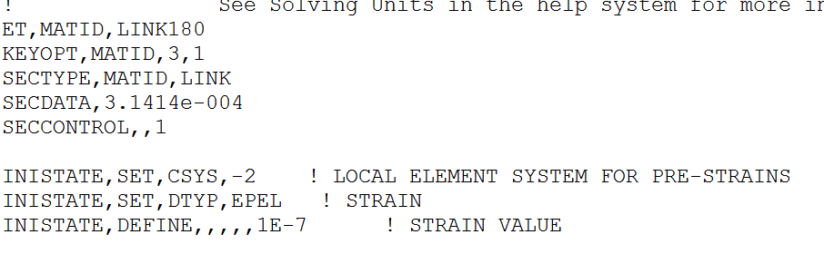
3. In the model --> geometry, add APDL commands as in the figure
September 26, 2020 at 8:47 ampeteroznewman
SubscribernWhenever you put numbers in a Command object that require the units to be set a certain way, it is best to go to Analysis Settings and set the Solver Units to Manual and set the system correctly as I have done below. By default, the solver will use whatever the units system you left Mechanical set to. In my case, I opened your file and it was set to mm. Is the cross-sectional area property in your Command in square meters or square mm? Without making the setting I show below, you will get a different solution depending on the current units setting.n I see you are using ANSYS 19.2 and that is important to say in case someone spends time fixing your model in a later version and you won't be able to open that file.nSince this is basically a 2D problem in the XZ plane, you can help the solver out by setting all the bodies to have a Y=0 displacement boundary condition.nWhen I run the model, there is this warning.n *** WARNING *** CP = 0.531 TIME= 04:14:00n For element type = 1 (LINK180), KEYOPT(3) = 1 is an undocumented option. nWhy are you using this?nWhen ANSYS solves the Statics problem, it is searching for equilibrium of all the forces. If you have drawn a perfect catenary shape and used the correct initial strain, then the solution would make no deformation.nANSYS will not consider self-weight if you don't turn on the Gravity load.nI can get a solution with the Force in the center.n
 You have one line body that you meshed with 43 beam elements, then converted those to link180 elements.nI don't know if the Command that converts Beam elements to Link elements has the same effect as setting the Model Type to Link in the Details.n
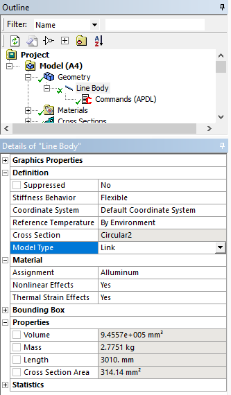 The problem is if you do that, you need 43 line bodies to be drawn in DesignModeler because you can only mesh one link element per line body.nBelow is the deformation with Gravity only, magnified 100 times. Maybe your initial catenary share has these errors in it, and ANSYS is providing the correct deformations. You could try drawing a straight line and then let ANSYS deflect it into a catenary shape and see what that looks like.n
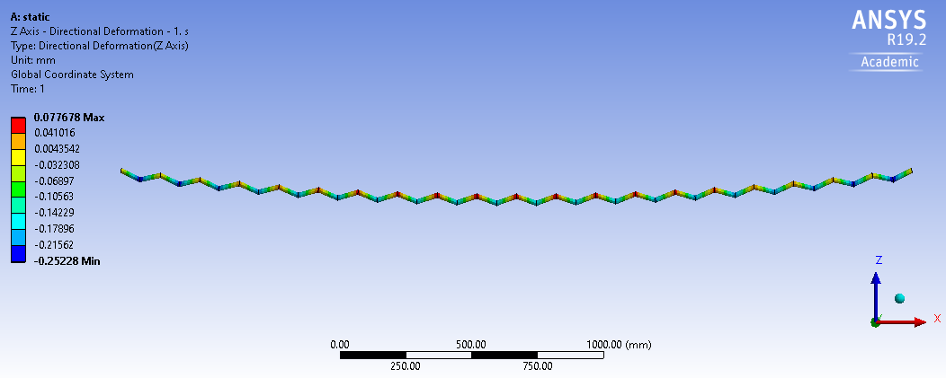 ANSYS 19.2 archive attached.n
September 27, 2020 at 8:56 pmSubscriberHello Peter,nThanks so much for your reply. But I still have some questions.nThe unit system I use in MD and Model is mks. The cross-section of the cable is the circle2 is 3.1415e-04 m^2. I don't know why when you open my file, the unit system becomes mm. Maybe this is because when I check the results, I changed the unit into mm. nThe command line 'keyopt(3)=1' is of nonsense. But this command doesn't make any change to the solutions. I added it in to my APDL command is because I paste and copy this command from previous one and forget it delete it.nThe geometry of the catenary shape of the cable I got is from SAP2000 built-in catenary element. The coordinate of the nodes and the end force is shown in the figure below. nIf I understand your suggestion correctly, you suggested to change the initial strain to be the actual strain which can be calculated as F/E/A = 1.4686e-06. After I changed the strain to be that value, the displacement of the cable under gravity is still a positive value. But as you suggested, if the initial strain value is correct, the displacement of the cable under graivity should be zeros.nI ran the model in the attached file. The purpose is that I would like to see what is the displacement of the cable under -10 N or even higher vertical load. But when I increased the vertical value to -10N, the solution diverge.nDo you have more suggestions?.Sincerely,nXiaon
ANSYS 19.2 archive attached.n
September 27, 2020 at 8:56 pmSubscriberHello Peter,nThanks so much for your reply. But I still have some questions.nThe unit system I use in MD and Model is mks. The cross-section of the cable is the circle2 is 3.1415e-04 m^2. I don't know why when you open my file, the unit system becomes mm. Maybe this is because when I check the results, I changed the unit into mm. nThe command line 'keyopt(3)=1' is of nonsense. But this command doesn't make any change to the solutions. I added it in to my APDL command is because I paste and copy this command from previous one and forget it delete it.nThe geometry of the catenary shape of the cable I got is from SAP2000 built-in catenary element. The coordinate of the nodes and the end force is shown in the figure below. nIf I understand your suggestion correctly, you suggested to change the initial strain to be the actual strain which can be calculated as F/E/A = 1.4686e-06. After I changed the strain to be that value, the displacement of the cable under gravity is still a positive value. But as you suggested, if the initial strain value is correct, the displacement of the cable under graivity should be zeros.nI ran the model in the attached file. The purpose is that I would like to see what is the displacement of the cable under -10 N or even higher vertical load. But when I increased the vertical value to -10N, the solution diverge.nDo you have more suggestions?.Sincerely,nXiaon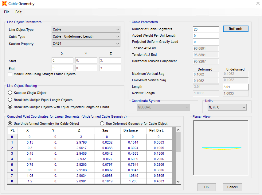 n
September 27, 2020 at 10:24 pmSubscriberThe model I uploaded above will solve with a -10 N Load.n
n
September 27, 2020 at 10:24 pmSubscriberThe model I uploaded above will solve with a -10 N Load.n September 27, 2020 at 10:55 pmSubscriberHello Peter,nThanks for your quick reply.nYes, this model can run under -10N in the Z directin.From SAP2000, I calculated the catenary shape and I extracted the end force from the cable under gravity. Then I applied the initial strain under that end force (tension under self-weight). But, still, the displacement under gravity is still positive. I really confused about this point. nThe APDL command i appled is based from this post /forum/discussion/5740/transmission-line-simulation. From this post, the APDL commands are used just to initiate the nonlinear lateral stiffness.nXiaoSeptember 28, 2020 at 12:29 amSubscriberUnder 10 N and gravity, the downward deformation was 10 mm, while under gravity only, the deformation upward was only 0.077 mm or 0.77% of the -10 N deformation. That is a small number. FEA solutions with less than 1% error are useful models.nSeptember 28, 2020 at 12:16 pm
ErKo
Ansys EmployeePeter is absolutely right here. We could not expect the deformation to be exactly zero under gravity, but as pointed out something quite small, and smaller than the deflections under applied forces.nnThank younnEriknViewing 6 reply threads- The topic ‘Single cable simulation using LINK180 element type’ is closed to new replies.
Innovation Space Trending discussions
 Top Contributors
-
peteroznewman
 6625
6625 -
scabo
 1906
1906 -
Dennis Chen
 1469
1469 -
javat33489
 1311
1311 -
Shyam Prasad V Atri
1022
Top Rated Tags
© 2026 Copyright ANSYS, Inc. All rights reserved.
Ansys does not support the usage of unauthorized Ansys software. Please visit www.ansys.com to obtain an official distribution.
-


The Ansys Learning Forum is a public forum. You are prohibited from providing (i) information that is confidential to You, your employer, or any third party, (ii) Personal Data or individually identifiable health information, (iii) any information that is U.S. Government Classified, Controlled Unclassified Information, International Traffic in Arms Regulators (ITAR) or Export Administration Regulators (EAR) controlled or otherwise have been determined by the United States Government or by a foreign government to require protection against unauthorized disclosure for reasons of national security, or (iv) topics or information restricted by the People's Republic of China data protection and privacy laws.
