

-
-
September 21, 2020 at 10:56 am
shal3391
SubscriberHi,
I am trying to model a liquid injection into a air flow.
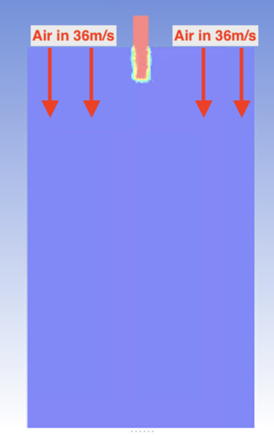
My domain is a 3D cylinder with a nozzle at the top, a cross section is attached.
I have a fluid velocity inlet at the nozzle of 4.3m/s and an air velocity inlet at the top of the cylinder of 36m/s.
I have currently selected an 'outflow' at the bottom, however the air velocity is increasing exponentially at this outflow. Shown in the figures attached.
What outlet boundary conditions should I use?
And do you have any recommendations regarding turbulence models, relaxation factors or solving schemes. Because I am also struggling choosing these parameters.
Many Thanks,
September 21, 2020 at 12:39 pmRob
Forum ModeratorUse a pressure outlet. Outflow is an old boundary dating back to before compressible flow and GUIs. nRe models and settings have a read through the documentation and come back with some suggestions and reasons for using a model or setting. nSeptember 21, 2020 at 10:58 pmSubscriberThanks Rob,nnAt the moment I am using the standard k-epsilon turbulence model because the majority of my fluid flow is far from any walls. However I am unsure if I need the turbulence dampening provided by the k-omega model. Would a k-epsilon realisable model or a k-omega SST model be an adequate compromise ?nMy goal is to induce fluid breakup in a jet stream, so I want there to be adequate turbulence fro this to happen. At the moment I am using the default values for all relaxation factors, would increasing the turbulent kinetic energy factor (default is 0. provide more accurate turbulence representation ? My understanding is to reduce the relaxation factors if the residuals are increasing, my residuals (attached) aren't necessarily increasing but don't look to be particularly stable.nI am currently using a SIMPLEC solving scheme (based on trial and error) but have read that a coupled scheme is generally better for VOF models. I am using a 'Compressive' volume fraction solver. I have also read that I should tick Pseudo Transient, but am unsure as to what it does.nI am using a variable time step to cap the Global Courant Number at 0.5.nThanks Again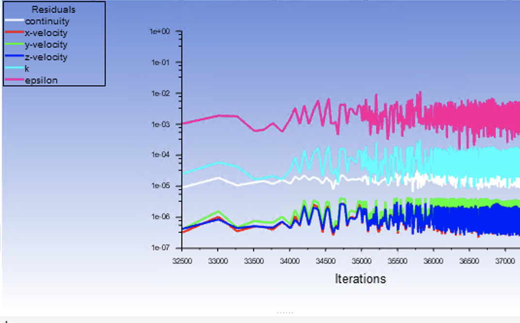 September 22, 2020 at 6:03 am
Keyur Kanade
Ansys EmployeePlease check nPlease check nAnd nArrayRegards,nKeyurnGuidelines for Posting on Ansys Learning ForumnHow to access ANSYS help linksnnViewing 3 reply threads- The topic ‘Outlet Boundary Conditions for VOF’ is closed to new replies.
Innovation Space Trending discussions
- air flow in and out of computer case
- Varying Bond model parameters to mimic soil particle cohesion/stiction
- Eroded Mass due to Erosion of Soil Particles by Fluids
- I am doing a corona simulation. But particles are not spreading.
- Centrifugal Fan Analysis for Determination of Characteristic Curve
- Guidance needed for Conjugate Heat Transfer Analysis for a 3s3p Li-ion Battery
- Issue to compile a UDF in ANSYS Fluent
- JACOBI Convergence Issue in ANSYS AQWA
- affinity not set
- Resuming SAG Mill Simulation with New Particle Batch in Rocky
Top Contributors
-
peteroznewman
 4067
4067 -
scabo
 1487
1487 -
Dennis Chen
 1308
1308 -
javat33489
 1156
1156 -
Shyam Prasad V Atri
1021
Top Rated Tags
© 2025 Copyright ANSYS, Inc. All rights reserved.
Ansys does not support the usage of unauthorized Ansys software. Please visit www.ansys.com to obtain an official distribution.
-


The Ansys Learning Forum is a public forum. You are prohibited from providing (i) information that is confidential to You, your employer, or any third party, (ii) Personal Data or individually identifiable health information, (iii) any information that is U.S. Government Classified, Controlled Unclassified Information, International Traffic in Arms Regulators (ITAR) or Export Administration Regulators (EAR) controlled or otherwise have been determined by the United States Government or by a foreign government to require protection against unauthorized disclosure for reasons of national security, or (iv) topics or information restricted by the People's Republic of China data protection and privacy laws.


