Dear Peteroznewman,nThank you always for your kind support. One more question, please? I have done a numerical analysis of the following experimental study, but I found the beam flanges' different deformation behaviors during the numerical analysis than the experimental results. Here, A, B, and C points are constrained. For example, A point C is assumed by fixed support while some directional DOFs are considered in the points A and B relatively given coordinate system. I have tried it by diverse variants of DOF to find accurate results in each point. It demands a lot of patience to finish the calculation time. n

Figure-1. General apparatus n

Figure-2. Front side buckling behaviors n

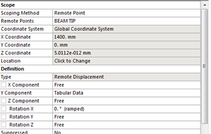
Figure-3. Back side buckling behaviors nFirstly, I assumed that the rotation Y is constant (0), and other DOF are free in the beam tip. In the point B, Z component and Rotation X are constant because I thought these two vertical columns fully constrained those movements. Unfortunately, the analysis shows me a different shape of deformation behavior than the experimental results. In the analysis shell elements are considered. n


Figure-4. Back and front side buckling behaviors. nSecondly, the rotation X is constant (0), and other DOF are free in the beam tip. In the point B, Z component and Rotation X are constant. Again the analysis shows me a different shape of deformation behavior than the experimental results. Here, the deformation behaviors of the first and second variants were similar. n


Thirdly, the rotation X and Y are constant (0), and other DOF are free in the beam tip. In the point B, Z component and Rotation X are constant. The analysis were terminated and again shows me a different shape of deformation behavior than the experimental results. n


How to know that which DOF of the point A and B acceptable in the numerical analysis? Could you check it out for me please? Please kindly see the attached file.nArrayUnurn


