
-
-
August 10, 2020 at 10:20 am
PD1029
SubscriberHello,
I am trying to simulate the Halbach array in flat magnet array configuration with samarium cobalt magnets. I have defined the polarization direction for each magnet by creating a coordinate system and duplicating the material property. I have successfully performed the simulation but I am not able to visualize the field distribution as shown in the figure. I tried different graphic settings using vector display but failed to achieve the desired field distribution. Should I change the analysis settings? or there should there be some changes in the graphic settings? Or do i have to generate a 2-D geometry for the 3-D model? Can anyone guide me here?
Thank you
August 10, 2020 at 12:56 pmicellb
SubscriberHi, nYou could draw a rectangle on the x-z plane cutting across your structure, then plot magnetic field on that plane only.nAugust 10, 2020 at 8:02 pmSubscriberdo you mean that i should create an enclosure around the geometry. I have already created the geometry, it is hidden in the image from the simulation result.nThank you for your reply.nStill It does not solve the issuenAugust 11, 2020 at 6:41 pmSubscriberHi, PD1029,nBy saying enclosure, I guess you meant the 3D region you created. What I meant was not a 3D enclosure but a 2D plane. To show the target field distribution, it is better to plot field on a plane rather than a 3D space. You just need to draw another plane (it will not affect your geometry or simulation), right click that plane and choose to plot B field. Hope I understood you correctly.nAugust 14, 2020 at 9:49 amSubscriberI tried creating zx plane. nI don't find the option to plot b-field. Could you please elaborate on how to proceed further?nThank you for your responses. Really appreciate your help.nI am attaching some pictures. Could you please take a look?n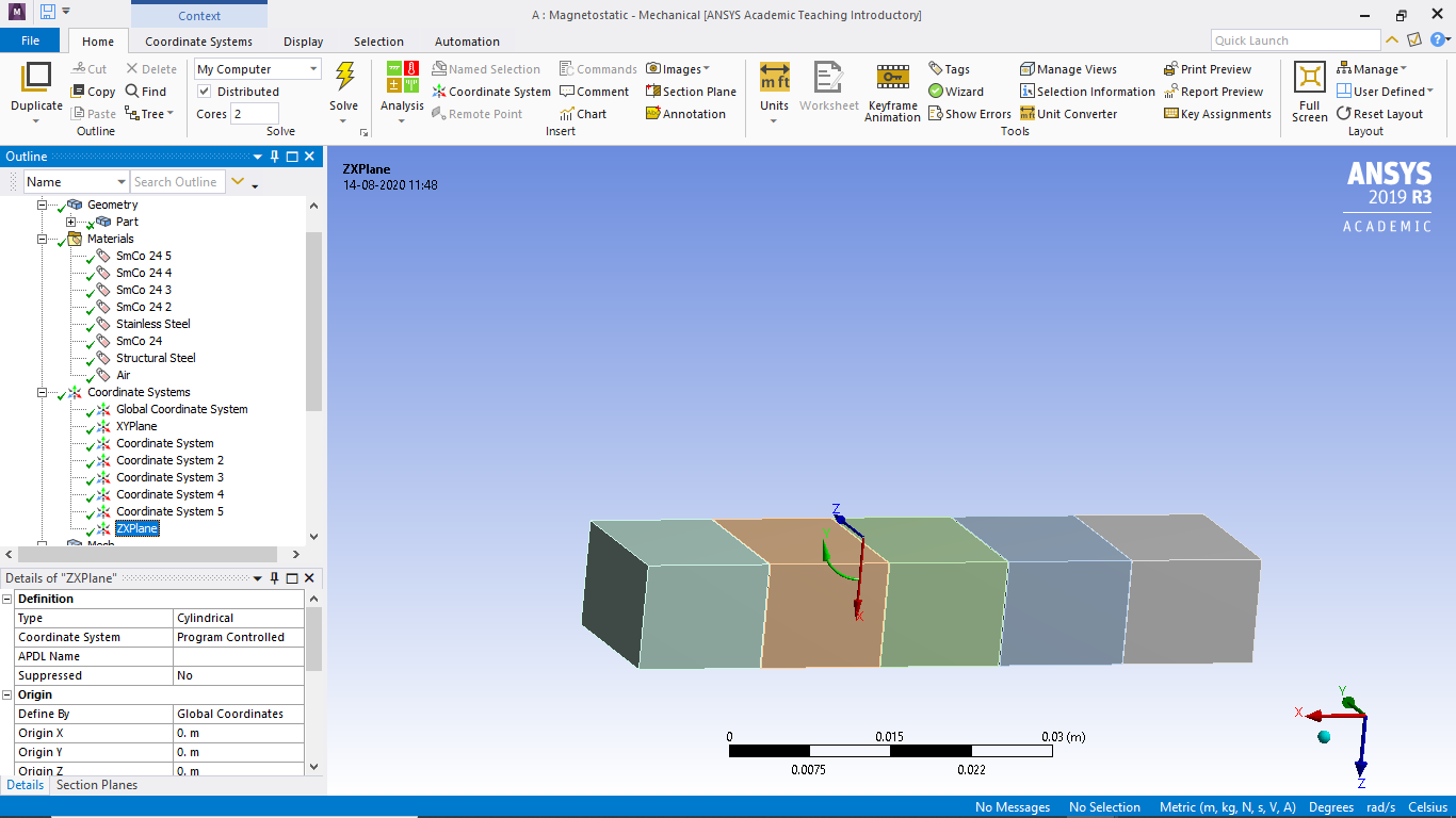
 n
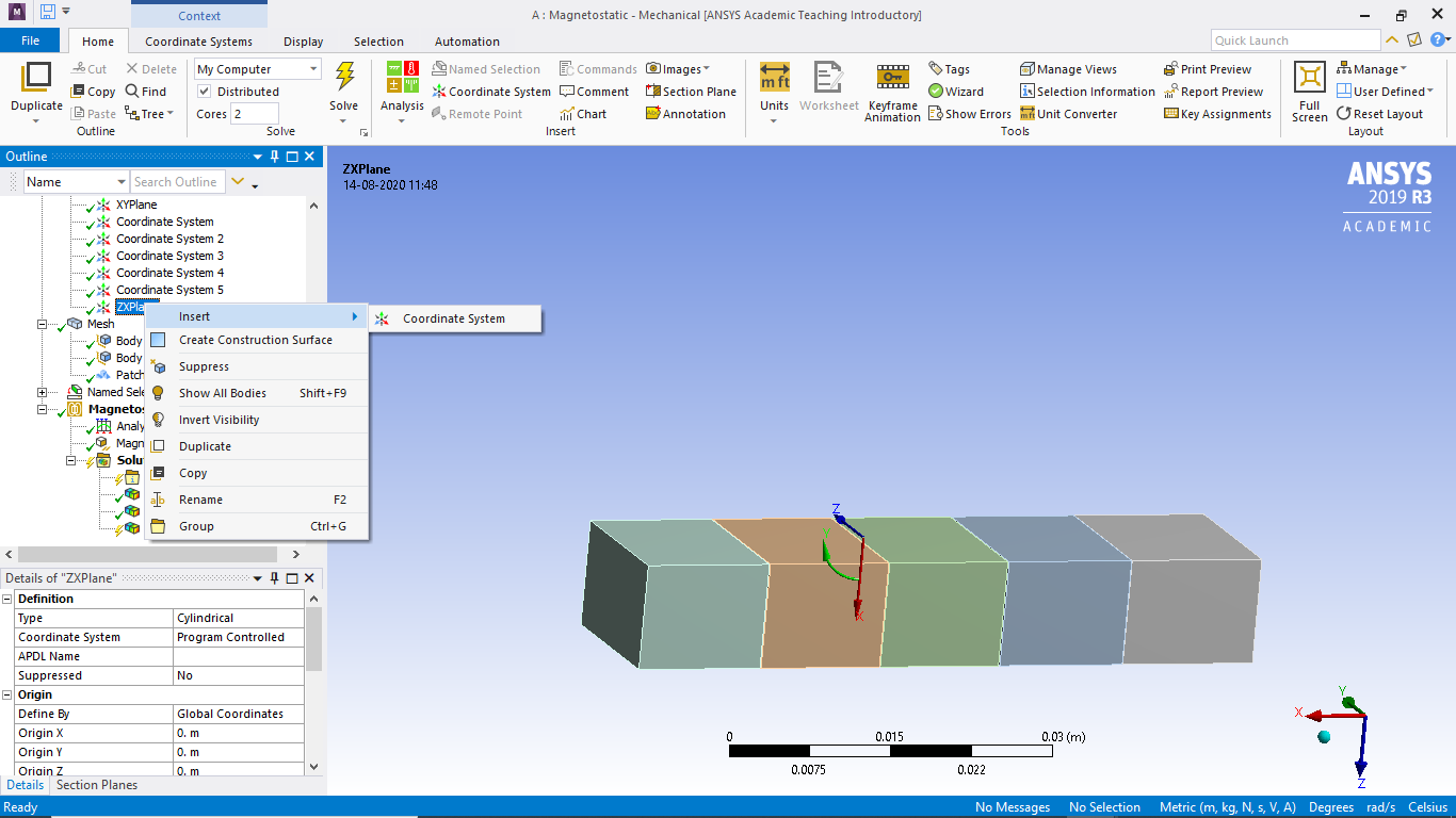
August 14, 2020 at 1:31 pmSubscriberHi,nRight click on that plane, choose field->B->Mag_B.nAugust 14, 2020 at 6:47 pmSubscribercould you take a look at the second image from my last comment. I right clicked, it does not show any option to plot the B field.nnAugust 20, 2020 at 9:53 amSubscriber,nKindly take a look at the question on top of the page.nCan you guide me on how to do visualize the magnetic field distribution in the flat magnet array?nI would really appreciate if you could advice me herenThank you nAugust 20, 2020 at 7:30 pm
n
August 14, 2020 at 1:31 pmSubscriberHi,nRight click on that plane, choose field->B->Mag_B.nAugust 14, 2020 at 6:47 pmSubscribercould you take a look at the second image from my last comment. I right clicked, it does not show any option to plot the B field.nnAugust 20, 2020 at 9:53 amSubscriber,nKindly take a look at the question on top of the page.nCan you guide me on how to do visualize the magnetic field distribution in the flat magnet array?nI would really appreciate if you could advice me herenThank you nAugust 20, 2020 at 7:30 pmpeteroznewman
SubscriberHello,nI believe you need to go back to CAD and add a large solid block around the magnets and assign that block the material property of air. nThe solid block must have a magnet shaped cavity at the center. SpaceClaim can do this for you by using the Enclosure tool.nYou also want to use the Share button on the Workbench tab to create shared topology so the mesh connects from the magnet to the air.nAugust 22, 2020 at 12:21 pmSubscribernI followed your advice. I created an enclosure and also used the share topology tool. Still I am not getting the desired result.nI want to get the result as shown in the figure belown nIn order to achieve the magnetic polarization, I created a duplicate material property and a co-ordinate system for each magnet and assigned the direction as demonstrated in the image above.nI am attaching the simulation results. Kindly take a look. My aim is to be able to show the field lines as shown in the Halbach array image. Do I have to change some analysis settings or it can be achieved by changing the visualization in the simulation?n
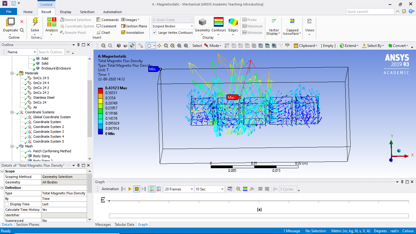
 nnIn the graphics, there are two options - uniform and proportional vectors. I have chosen proportional to in order to visualize the field distribution. Since, the vectors with blue color shows 0T it is of no use. However, I have provided an image below showing with the uniform vector selection. Kindly guide me here, what has to be done.n
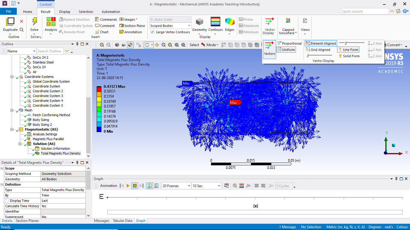 nThank you very much for your time.n
August 22, 2020 at 1:50 pmSubscriberYou will have better control if you plot contours rather than vectors.nI agree with that you want to plot those on a Construction Plane, but put that plane through the center of the magnets, not on the surface.nIt will be best to plot the air body only and not all bodies and you can use the Scope line in a result plot to do that.nThe legend on a contour plot is very adjustable. You can start off by choosing between linear and logarithmic spacing. You can increase the number of contour bands, you can change the plot from solid fill to lines, and you can adjust individual iso levels all on the legend.nIf you clear out the mesh, and save the model, you can do a File, Archive to create a .wbpz file. You can use the paperclip icon in your reply to attach that file. Then I can try out on your model what I have suggested above.nAugust 23, 2020 at 4:28 pmSubscriber, thank you very much for the detailed explanation. I followed your advice and applied it in the simulation.nnI am attaching the image from the simulation result below with vector display and isolines:nResult for all bodies(vector display):n
nThank you very much for your time.n
August 22, 2020 at 1:50 pmSubscriberYou will have better control if you plot contours rather than vectors.nI agree with that you want to plot those on a Construction Plane, but put that plane through the center of the magnets, not on the surface.nIt will be best to plot the air body only and not all bodies and you can use the Scope line in a result plot to do that.nThe legend on a contour plot is very adjustable. You can start off by choosing between linear and logarithmic spacing. You can increase the number of contour bands, you can change the plot from solid fill to lines, and you can adjust individual iso levels all on the legend.nIf you clear out the mesh, and save the model, you can do a File, Archive to create a .wbpz file. You can use the paperclip icon in your reply to attach that file. Then I can try out on your model what I have suggested above.nAugust 23, 2020 at 4:28 pmSubscriber, thank you very much for the detailed explanation. I followed your advice and applied it in the simulation.nnI am attaching the image from the simulation result below with vector display and isolines:nResult for all bodies(vector display):n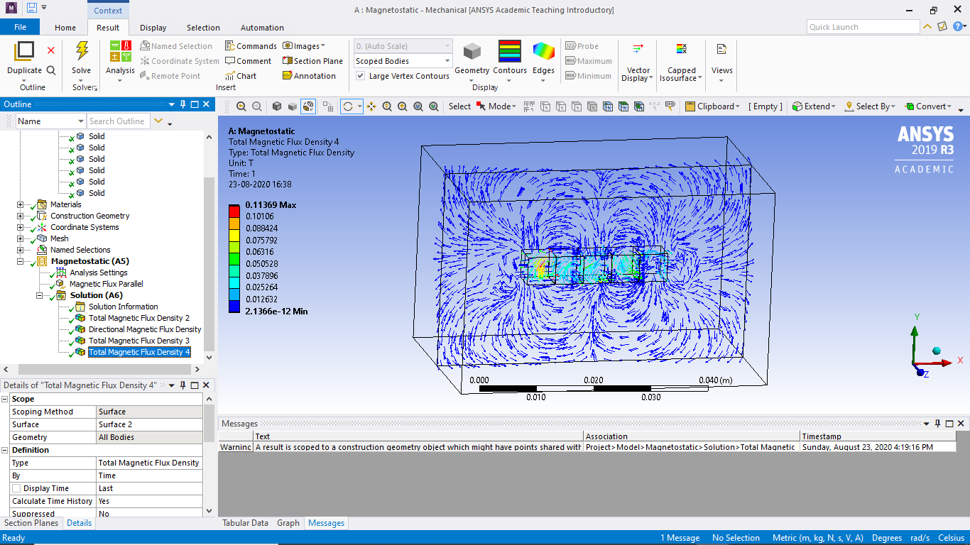 Result for enclosure(vector display):n
 Result(isolines):n
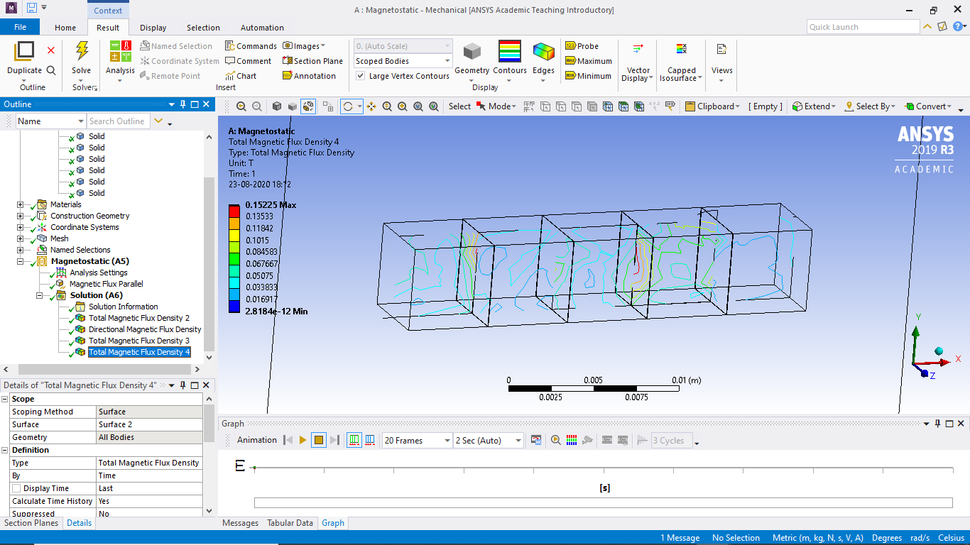 nnAlso, i tried attaching the project file in .wbpz format. this format is not allowed i guess. So, i have attached a .rar file. I am not quite sure if that works. I think you will be able to open the zip(.rar) file. Once again, thank you for your time and advice.nn
August 23, 2020 at 8:55 pmSubscriberThe .rar file has the _files folder but not the 5 magnets(construction plane).wbpj file which is also required. Without that file, I cannot open the project.nIf you created a .wbpz file, you should have put that in the .rar file because both the .wbpj file and the _files folder are combined into one file when your write out a .wbpz file.nnAugust 23, 2020 at 11:15 pmSubscriber,I have attached both the files .wbpz and .wbpj. I hope you will now be able to open itnAugust 25, 2020 at 1:49 amSubscriberI was able to do some work on this model, but only in 2020 R1, so unfortunately, you can't open the model I worked on.nI changed all the Extrudes from Add Material to Add Frozen. That let me edit all the sketches so there was no air gap between the magnets. Those small gaps just made meshing the air to be inefficient. Once the blocks all touched, the air could be meshed more efficiently. I used 10 planes to slice the air up into blocks so that it could be meshed with 0.5 mm cubes. The mesh has 2.2M nodes and 539,000 elements.n
nnAlso, i tried attaching the project file in .wbpz format. this format is not allowed i guess. So, i have attached a .rar file. I am not quite sure if that works. I think you will be able to open the zip(.rar) file. Once again, thank you for your time and advice.nn
August 23, 2020 at 8:55 pmSubscriberThe .rar file has the _files folder but not the 5 magnets(construction plane).wbpj file which is also required. Without that file, I cannot open the project.nIf you created a .wbpz file, you should have put that in the .rar file because both the .wbpj file and the _files folder are combined into one file when your write out a .wbpz file.nnAugust 23, 2020 at 11:15 pmSubscriber,I have attached both the files .wbpz and .wbpj. I hope you will now be able to open itnAugust 25, 2020 at 1:49 amSubscriberI was able to do some work on this model, but only in 2020 R1, so unfortunately, you can't open the model I worked on.nI changed all the Extrudes from Add Material to Add Frozen. That let me edit all the sketches so there was no air gap between the magnets. Those small gaps just made meshing the air to be inefficient. Once the blocks all touched, the air could be meshed more efficiently. I used 10 planes to slice the air up into blocks so that it could be meshed with 0.5 mm cubes. The mesh has 2.2M nodes and 539,000 elements.n
 Now when I change the direction of the coordinate systems to match the original diagram, I get this:n
 Note: I don't know how to use Magneto-Statics, but this seems to be closer to what you want.n
August 25, 2020 at 3:19 amSubscriber
Note: I don't know how to use Magneto-Statics, but this seems to be closer to what you want.n
August 25, 2020 at 3:19 amSubscriber August 27, 2020 at 3:26 pm
wrbulat
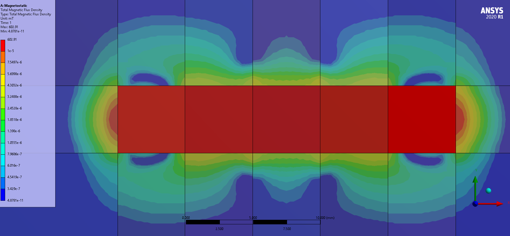
Ansys EmployeeI think the problem is this:the image depicts magnetic fluxlines. Fluxlines are lines along which the magnetic flux density B is parallel. In 3D magnetic models, I think the field results image that is closest to this (but NOT the same thing) is a vector plot of B, which I can see you have created. The vectors are also parallel to B, but they are in general not aligned as the fluxlines are.nUsing 2D models it IS possible to plot fluxlines (by making contour plots of AZ - the nodal degree of freedom that represents the out of plane component of the magnetic vector potential demoted in the literature as A). If you create a 2D planar model which is a cross section of the Halbach array, it should allow you to create a plot of fluxlines.nnAugust 27, 2020 at 3:53 pmAnsys EmployeeI should add that I think the 3D analogy to fluxlines are called fluxtubes:nnnand that the results of a 2D planar model of the Halbach array cross section will differ somewhat from those calculated at the cross section by a 3D model because the 2D planar model assumes no field variation in the z direction (normal to the plane of the model).nSeptember 16, 2020 at 10:14 amSubscribersorry for the delayed response. I had examinations in the month of August and September, that is why i was not able to work on the model and could not reply here.nnThe model you worked on in ANSYS 2020 R1, that is what I was trying to do.Could you explain to me how did you eliminate the air gaps between the magnets? How were you able to mesh that? So that I can also achieve the same results.nnThank you very much. Really appreciate your help.nSeptember 16, 2020 at 3:54 pmSubscriberI eliminated the air gaps by editing each sketch that created them in the first place. I moved a line in the sketch for one block so that edge was coincident with the adjacent block. I edited each block until all the air gaps were gone.nSeptember 29, 2020 at 6:49 amSubscribernnI was successfully able to do all of it but as you can see in the picture below, the visualization is still not the same as yours. I followed your advice and eliminated the air gaps. I am using ANSYS student. Is it because of the size limits of the elements and nodes? In the student license the nodes and number of elements are limited to 32,000 only. ANSYS does not allow elements than 32,000.n n
September 29, 2020 at 9:26 pmSubscriberYes, my mesh had 2.2 million nodes, so I got nice smooth contours. Your contours will be more choppy.nOctober 12, 2020 at 8:45 amSubscriberhope you are well! I have now installed the ANSYS 2020 R1. Could you share the file you worked on, It will be really helpful. Thank you very much and have a nice day. nViewing 22 reply threads
n
September 29, 2020 at 9:26 pmSubscriberYes, my mesh had 2.2 million nodes, so I got nice smooth contours. Your contours will be more choppy.nOctober 12, 2020 at 8:45 amSubscriberhope you are well! I have now installed the ANSYS 2020 R1. Could you share the file you worked on, It will be really helpful. Thank you very much and have a nice day. nViewing 22 reply threads- The topic ‘Magnetostatics analysis system – Magnetic flux density distribution (not Maxwell 2D or 3D)’ is closed to new replies.
Ansys Innovation Space Trending discussions
 Top Contributors
-
peteroznewman
 3762
3762 -
scabo
 1333
1333 -
Dennis Chen
 1168
1168 -
javat33489
 1090
1090 -
Shyam Prasad V Atri
1014
Top Rated Tags
© 2025 Copyright ANSYS, Inc. All rights reserved.
Ansys does not support the usage of unauthorized Ansys software. Please visit www.ansys.com to obtain an official distribution.
-


The Ansys Learning Forum is a public forum. You are prohibited from providing (i) information that is confidential to You, your employer, or any third party, (ii) Personal Data or individually identifiable health information, (iii) any information that is U.S. Government Classified, Controlled Unclassified Information, International Traffic in Arms Regulators (ITAR) or Export Administration Regulators (EAR) controlled or otherwise have been determined by the United States Government or by a foreign government to require protection against unauthorized disclosure for reasons of national security, or (iv) topics or information restricted by the People's Republic of China data protection and privacy laws.


