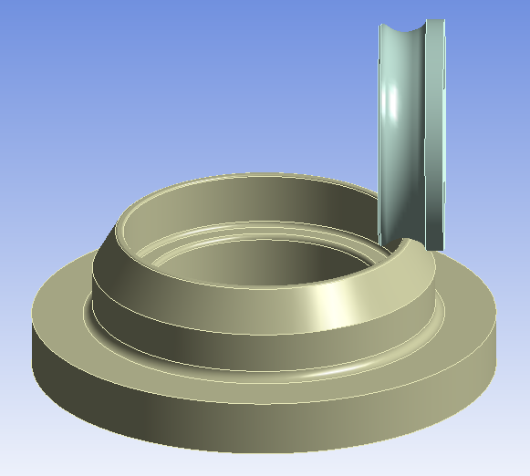
What materials are the two bodies made from?(bottom part is aluminum and roller part is structural steel)
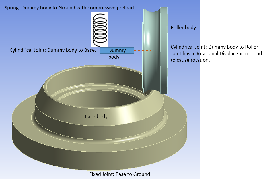
How is each body supported? What DOF are free on each body?
The bottom part is fixed and having the frictional contact between each other.
The roller part is free to rotate.
Which body has a motion input?
The roller part green one.
Is the roller body the green one? yes
Does the roller body have frictional contact with the other body?
yes it has(0.25)
Is there a force that pushes the roller body down onto the rib of the other body (and a translational DOF to allow the roller body to move up and down) or is the roller body on a fixed axle and deformation in the materials takes care of the interference between the bodies?
yes there is a force on the roller that pushes the rib of the bottom part.The Y - direction is free to translate up and down.
the bottom part axle rib has to deform and the roller part is rigid with no deforamation is allowed.