Ansys Assistant will be unavailable on the Learning Forum starting January 30. An upgraded version is coming soon. We apologize for any inconvenience and appreciate your patience. Stay tuned for updates.
General Mechanical

General Mechanical

Topics related to Mechanical Enterprise, Motion, Additive Print and more.

Modelling clamp support for heater coil

    • noureldin.ahmed30
      Subscriber

      Hello,


      I am analysing the effect of thermal displacement generated by heater coil on the respective nozzle. I have modelled the coil as 1D beam element with predefines pipe cross section. In reality, this coil is supported by 4 u bolts around its circumference as illustrated on attached image. I am not interested on the stresses generated on the u bolt rather, want to capture its effect on the coil weight and displacement due to the thermal strain. What is the most effecient way to model this support?

    • peteroznewman
      Subscriber

      The U-bolts appear to only support the weight of the coil. There seems to be clearance to allow the coil to move radially and tangentially.  I suggest you apply a Y = 0 displacement boundary condition on each node of the coil where the U-bolt touches the coil. That will leave the X and Z directions free to have some thermal expansion displacement of the coil in those directions.  You can check the reaction forces to make sure they are all positive, indicating that the constraint is supporting the weight of the coil. If a node shows a negative reaction force, that means the coil wants to lift off that supporting U-bolt. If that happens, you could simply suppress that BC or add a gap element that prevents deformation in the -Y direction but allows deformation in the +Y direction.

    • noureldin.ahmed30
      Subscriber

      Thanks Peter. I added displacement supports on the four locations where the coil is supposed to be supported. I summed the total reaction forces on the four locations in addition to the top heaters plate and the sum is exactly equal to the total weight of the system and all the reaction forces are positive. I have another two questions:

      1- If I modelled these supports like cylinderical or translation joints, was this a proper choice?

      2- The intent of this model is to calculate the thermal fatigue effect of the coil on the top reinforcement plate which is cracked already. And this coil normally operates at  344 C and subjected to cyclic operation (from ambient to operating temperature and so on). Should I first model the thermal behaviour on steady state analysis or transient analysis and link the output to structural analysis or I can input the thermal condition directly on the structural analysis model?

    • peteroznewman
      Subscriber

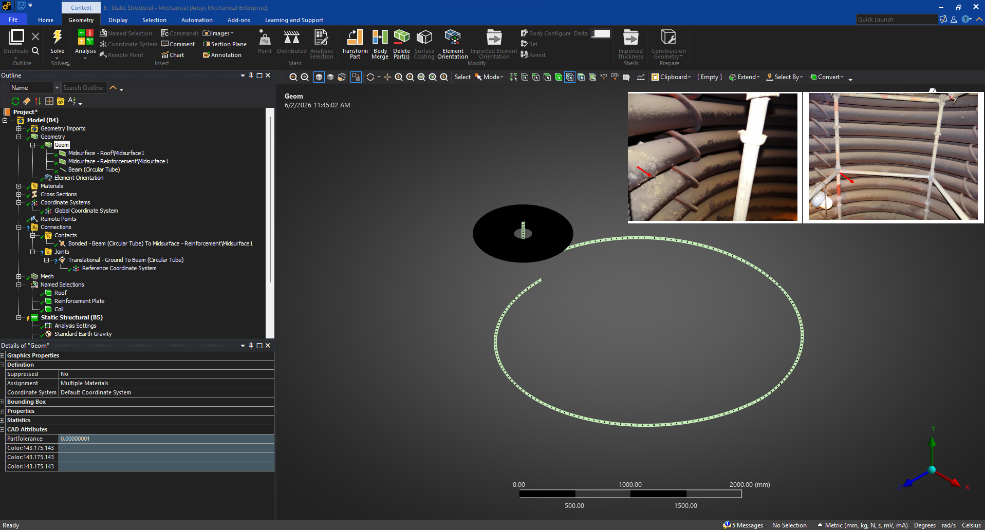
      The U-bolts basically provide a point contact between two cylinders crossing at an angle.  The only constraint is translation in Y, leaving five degrees of freedom Free.  It would be wrong to use a Translational joint because that would prevent all rotational degrees of freedom and two translationaly degrees of freedom which is not at all like how the coil sits on the bottom leg of the U-bolt.

      Static Structural is the correct analysis. Transient Structural is unnecessary because the velocity of the parts are practically zero so the inertia forces that the transient analysis adds to the static analysis are all practically zero.

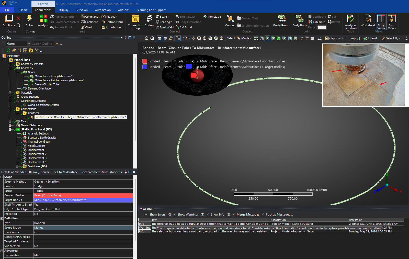
      Static Structrual can have two load steps. Both load steps include Standard Earth Gravity.  Load Step 1 has a Thermal Condition of ambient temperature.  Load Step 2 has a Thermal Condition of 344 C on the coil body.  The stress amplitude in the reinforcement plate between these two steps is what drives fatigue failure.

      If the plate geometry is of the original design, the analysis can predict that a fatigue failure is expected and show the location where a crack may start.  You already know where the crack is and its length. If you put the crack in the plate geometry, you can calculate the crack length growth on each thermal cycle.  Drilling a large diameter hole at the crack tip is a well-known crack growth arresting mitigation. You could model that geometry and see if a new crack is expected.  If you are going to replace the reinforcement plate with a new part, you can model geometry of an improved design and see if a crack is expected in the new design.

Viewing 3 reply threads
  • You must be logged in to reply to this topic.
[bingo_chatbox]