Hello,
I am working with ANSYS ACP 2024 R2 and have a problem with the visualization of shell normals and fiber orientations on a cylindrical shell.
Model:
- Simple cylindrical shell geometry
- Cylindrical Rosette with the axis aligned to the cylinder axis
- Shell body imported from Mechanical
- Composite layup assigned successfully
Problem:
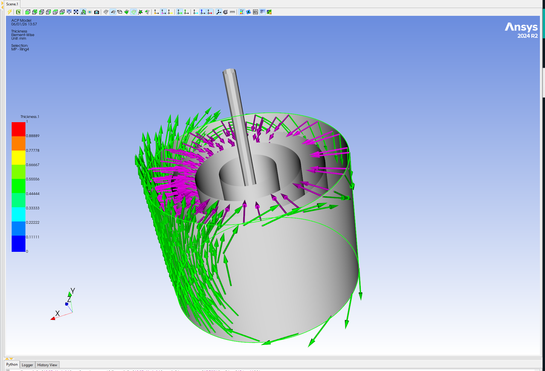
When I display the shell normals and fiber orientations, the arrows appear only on approximately one half of the cylindrical surface. On the remaining part of the cylinder, very few or no arrows are shown at all.
The cylinder is a continuous surface and I would expect the normals and orientation vectors to be displayed uniformly around the entire circumference.
I have already checked:
- Rosette definition
- Coordinate system alignment
- Shell element orientation
- Mesh quality
However, I have not been able to identify the cause.
My concern is that this issue may be related to the non-axisymmetric results I am obtaining later in the structural analysis.
Has anyone encountered a similar problem or can explain why ACP displays the normals and orientation vectors only on part of the cylindrical shell?
I have attached a screenshot showing the normals (green) and orientation vectors (magenta).
Thank you for your help.