Ansys Assistant will be unavailable on the Learning Forum starting January 30. An upgraded version is coming soon. We apologize for any inconvenience and appreciate your patience. Stay tuned for updates.
3D Design

3D Design

Topics related to Ansys Discovery and Ansys SpaceClaim.

2D contact problem – steel base deforms although it should be rigid

    • flying3tiger3
      Subscriber

      Hello,
      I am working on a 2D ANSYS Mechanical model with contact between a soft ellipse and a steel base.

      Setup:

      • Ellipse = soft material, e.g. Aluminium Alloy
      • Base = steel (very stiff)
      • Displacement applied to the ellipse
      • Bottom of base is fixed

      Problem:
      The steel base shows visible deformation, although it should behave almost rigid compared to the soft body.

      If I (incorrectly) define the top line of steel base as target, the result looks correct (no deformation of the base).

      Question:
      Why does the steel deform in the correct setup? How can I fix this while keeping the bottom of the base fixed?

      Best Regards

      Displacement: ellipse       Bottom line of base: fixed


      Displacement: ellipse       Top line of base: fixed


      Displacement: ellipse       Bottom line of base: fixed

    • peteroznewman
      Subscriber

      Young's Modulus of Steel is 200 GPa, while Aluminum is 71 GPa so Steel is only 2.8 times stiffer than Aluminum. This is not what I would call a very big difference in stiffness. Polyethelene has a Young's Modulus of 1.1 GPa which is getting to be a big difference in stiffness.

      The accuracy in your results for steel is low because you have only 2 elements through the thickness of the steel plate. Use the same element size in the steel as you used in the ellipse.

      Is this a Plane Strain model or a Plane Stress model?  It should be Plane Strain.

    • flying3tiger3
      Subscriber

      Thank you for your answer.

      1. Aluminium was only an earlier test case. In the current model I use:
      - base/surface: Structural Steel, E = 2e5 MPa
      - ellipse: linear elastic material, E = 0.08 MPa

      So in this case the stiffness difference is very large.

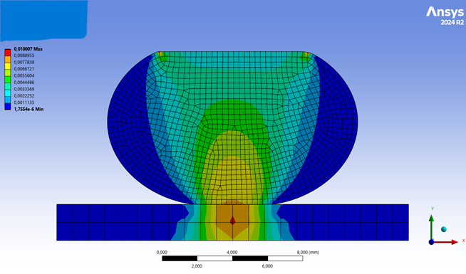
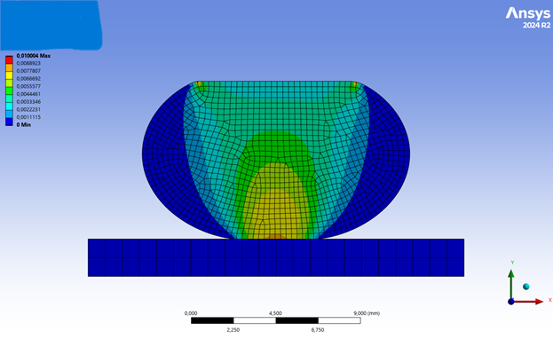
      2. I also refined the mesh of the steel base and used approximately the same element size as in the ellipse, but the deformation of the base still remains almost unchanged.

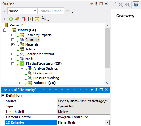
      3. Regarding Plane Stress / Plane Strain:

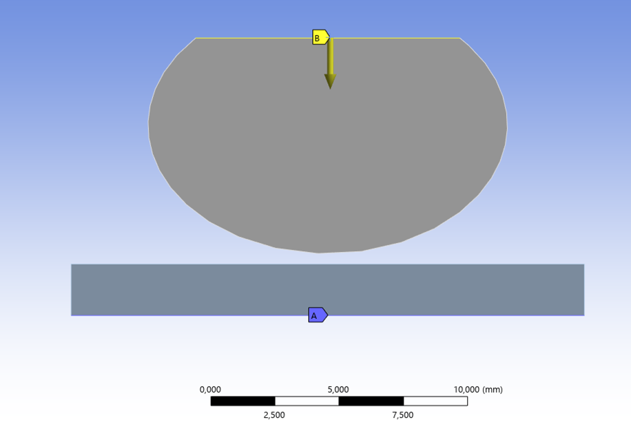
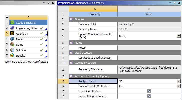
      The model is intended to represent a 2D cross-section.
      However, in Mechanical my bodies are defined as shell bodies (one of them has a thickness assigned; I created it by extruding and cutting the ellipse), so I believe ANSYS is actually using a Plane Stress formulation.

      How can I change this to a Plane Strain model?

      Could this be the reason for the unexpected deformation of the steel base?

    • peteroznewman
      Subscriber

      Here are the steps required to build a 2D plane strain model.

      1. Draw surface bodies in the global X-Y plane (Z=0).
      2. In Workbench, on the Geometry cell, in the Properties window, set the Analysis Type to 2D.
      3. Open the Model in Mechanical and under the Geometry branch, set the 2D Behavior to Plane Strain. 
        In the details window for the body, there is no thickness value.

      The results are in terms of Unit Depth.  This means if you are working in mm, the results are per mm of depth.  If you are working in m, the results are per m of depth. If you are working in inches, the results are per inch of depth.

      For example, if the reaction force is 2.34 N and you are working in mm, and the real object is 100 mm in the Z direction, the total force for that 100 mm long object is 234 N.

      Also, if you change units from mm to m and solve the model, the reaction force will be reported as 2340 N, but then you would multiply by the object length in Z which is 0.1 m to get the same 234 N for the real object.

Viewing 3 reply threads
  • You must be logged in to reply to this topic.
[bingo_chatbox]