Hello Ansys Community,
This is a pretty niche question but I have been having trouble with it for a little while and haven't been able to work out a fix.
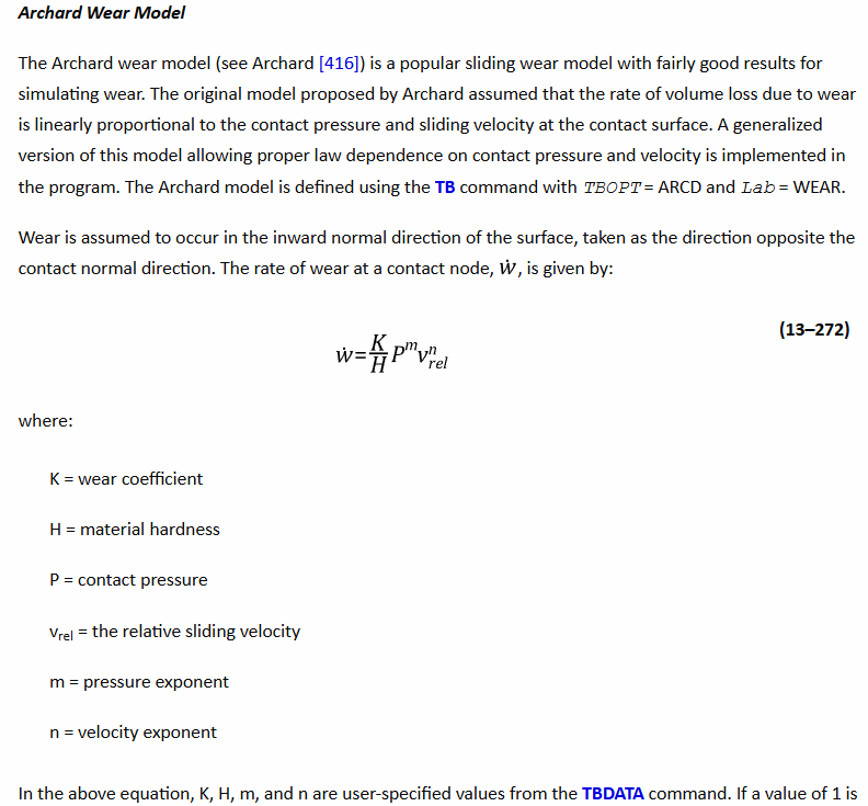
Pretty much I am working on a model for a Pin-On-Disc wear test, I am moddelling it in two dimensions so that it can solve quickly and have applied the following remshing constraint, where conwearel are the contact elements in Figure 4 (the curved surface is the contact elements the top flat surface are MPC contact elements and the lower flat surface is the target surface).
nlad,conwearel,ADD,contact,wear,0.2
nlad,conwearel,ON,ALL,ALL,1,,TravelDistance+1
This works are morphing most of the nodes (see figure 2 and 3 for before and after morphing has been applied duering the wear model), however the nodes along the axisymmetric line do not morph meaning that for longer distances and hence greater wear depths (or for finer meshes), the axisymmetric nodes drop below the target elements the model becomes unstable and crashes.
My qusetion as a result is weather there is a way to apply the wear on the curved contact surface that not only morphs the underlying nodes but also the nodes along the axisymmetric line?
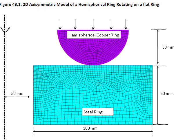
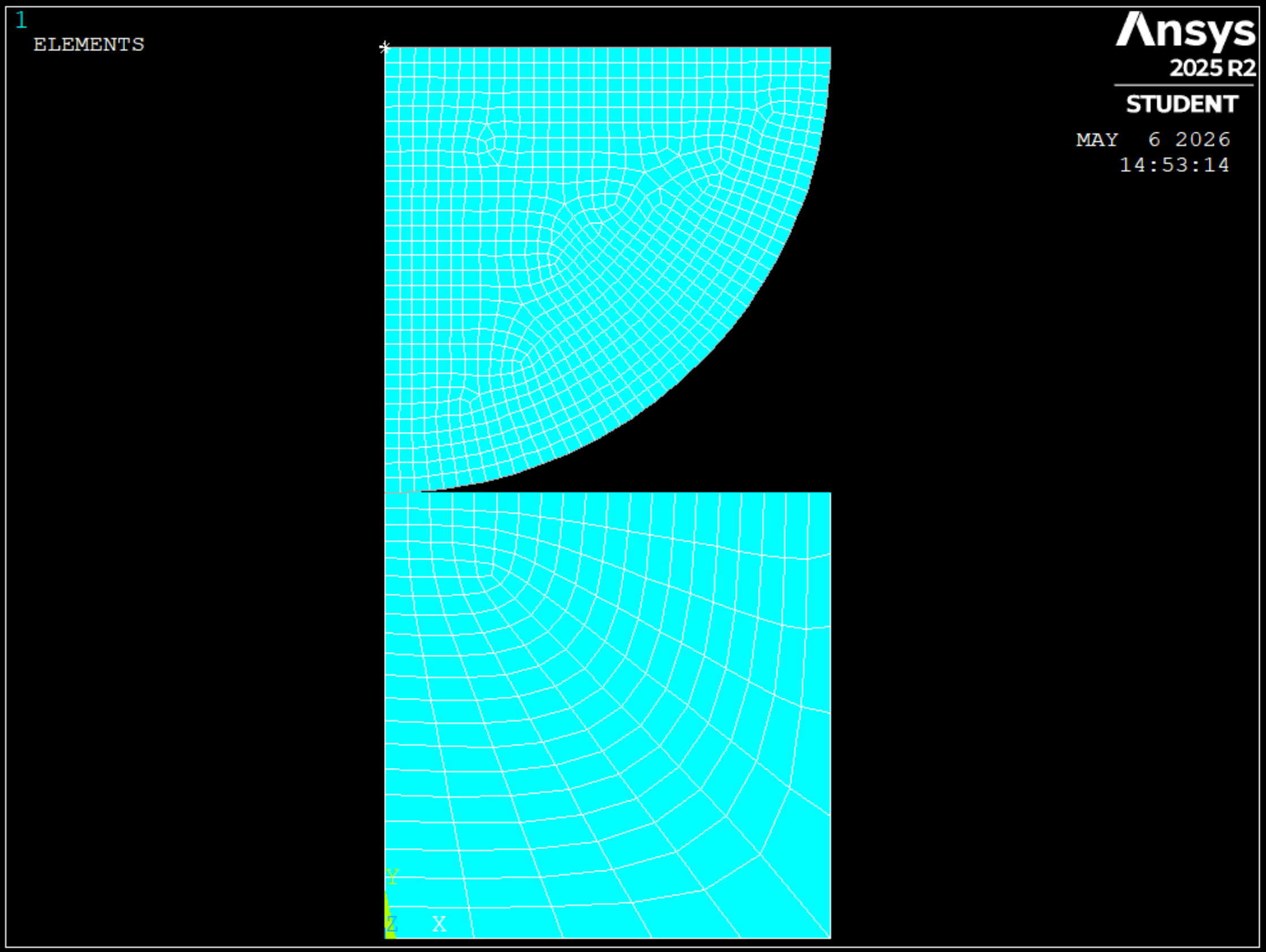 Figure 1.
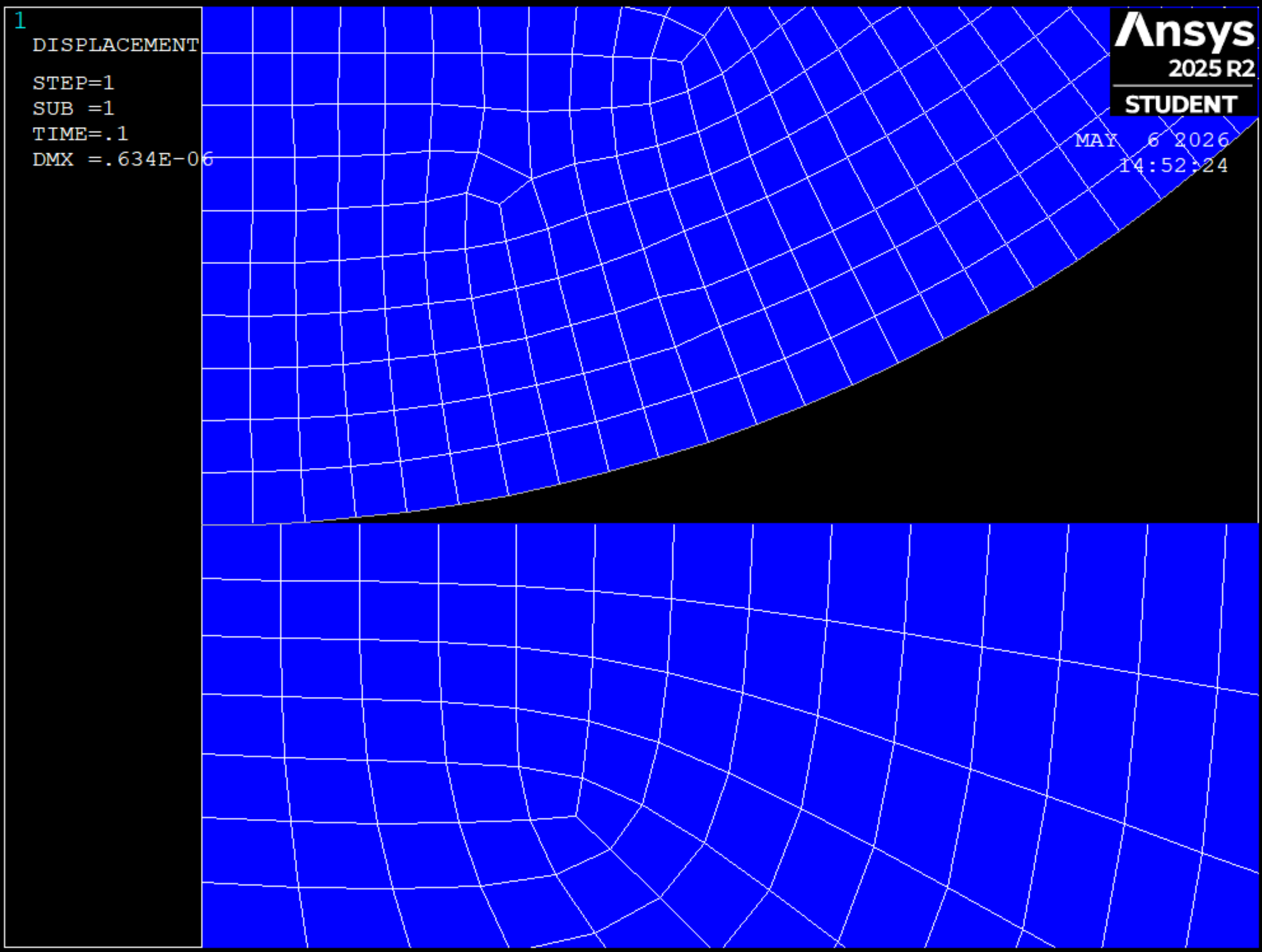 Figure 2.
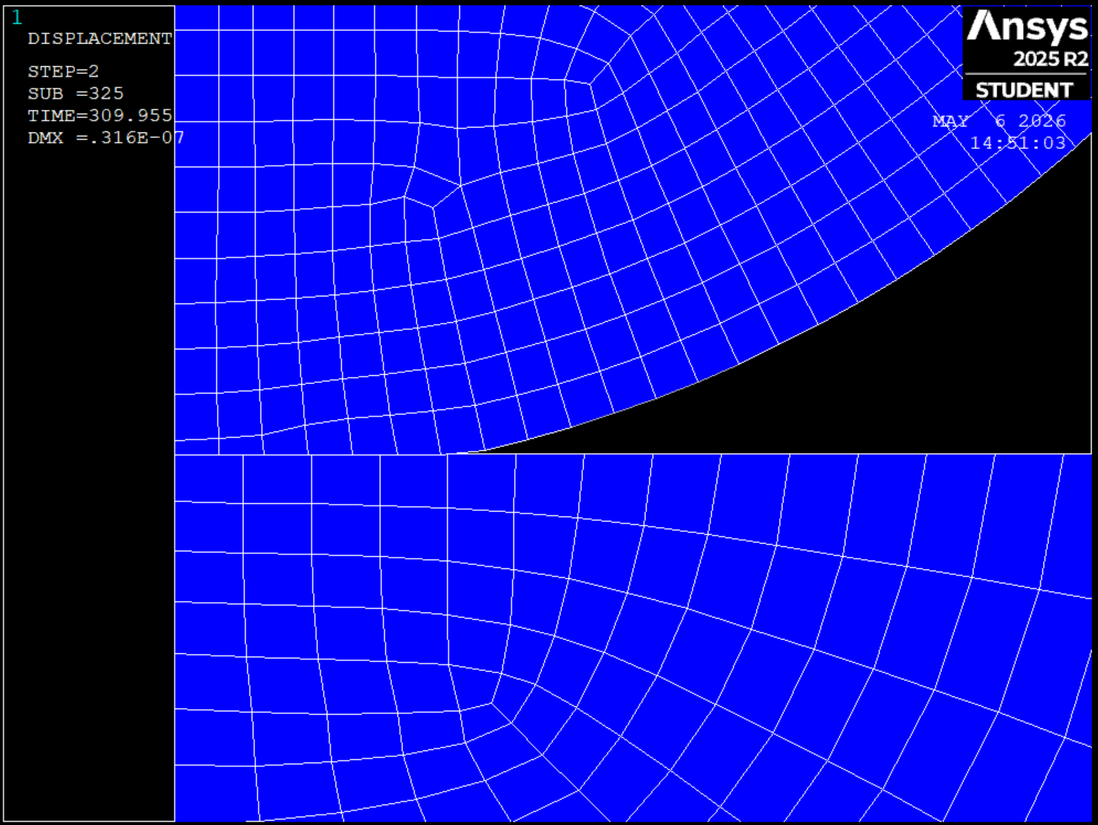 Figure 3
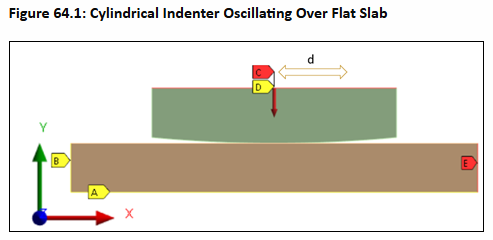
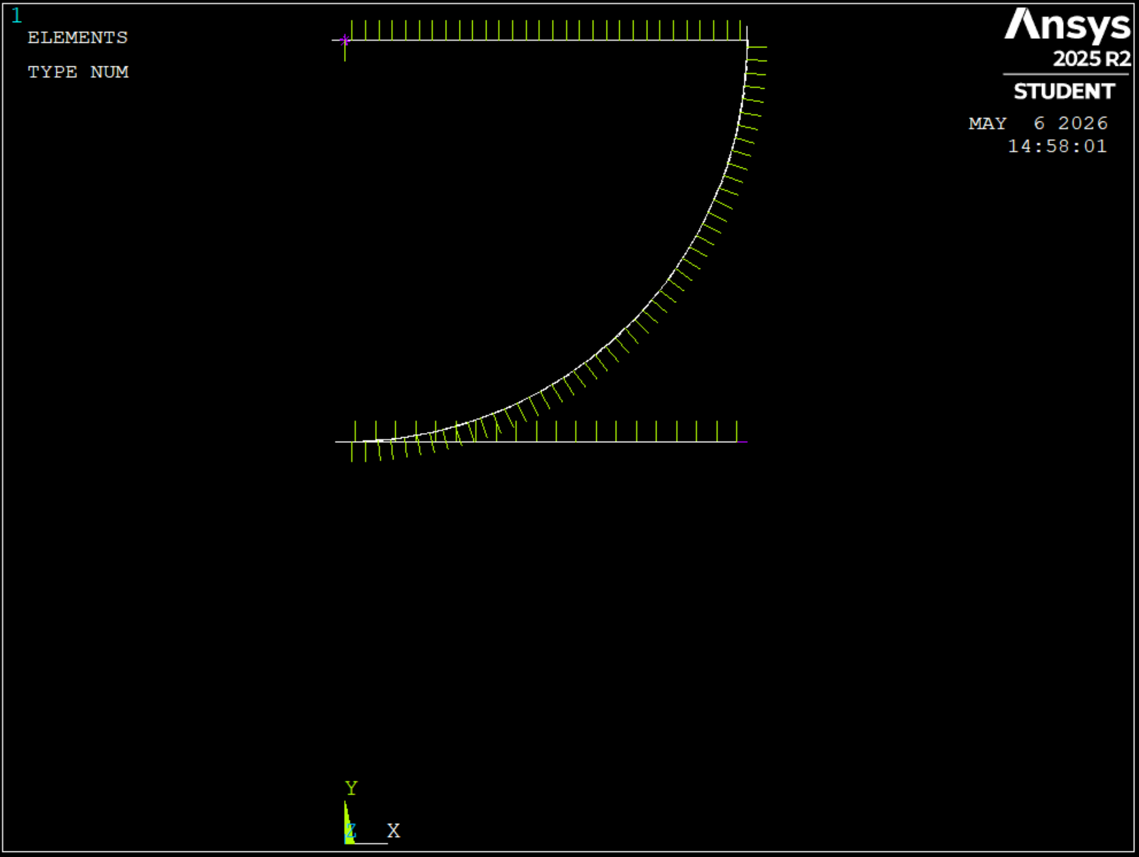 Figure 4.