-
-
May 2, 2026 at 6:10 am
kallvianaansaputra
SubscriberHi everyone,
I am currently working on a 3D simulation of a centrifugal pump (using MRF approach) in ANSYS Fluent. My impeller uses a logarithmic spiral blade profile. However, I have been stuck for days trying to generate a good mesh in ANSYS Meshing.
Geometry & Constraints:
There is a very narrow 1 mm gap between the impeller and the volute casing.
My supervisor specifically requires me to apply Inflation Layers on the impeller blades using the "First Layer Thickness" option to capture the boundary layer accurately.
The Problems / Errors Encountered:
Attempt 1: The "Crash"
Initially, I used the Patch Conforming Method for the impeller and applied a First Layer Thickness of around 2e-5 m to 5e-5 m on the blades. The mesher failed to complete and gave me these errors:
"The inflation layer generation did not complete. This may be due to poor quality patches in the surface mesh, sharp geometric features, or narrow passages."
"Patch conforming tetrahedron mesh generation did not complete..."
(I suspect the 1 mm gap is too tight for the inflation layers to grow without colliding).
Attempt 2: The "Zero Quality"
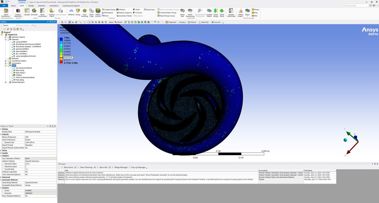
I tried to tweak the settings by using the Hex Dominant Method for the casing/pipes and kept Patch Conforming for the impeller, while forcing a very thin first layer (5.7e-6 m). The mesh successfully generated (reached 100%), but it gave me warnings and completely destroyed the mesh quality:
"Inflation created stairstep mesh at some locations."
My Minimum Orthogonal Quality dropped to 5.17e-12 (essentially zero), which obviously will diverge in Fluent immediately.
[IMG]
[/IMG]
My Questions for the Experts:
What is the best meshing algorithm (Patch Conforming vs Patch Independent) for highly curved centrifugal blades trapped in a very tight (1 mm) casing gap?
How can I successfully apply a specific First Layer Thickness on the blades without causing elements to squish or collide in that 1 mm gap? Is enabling "Layer Compression" under Collision Avoidance sufficient, or are there better tricks?
To avoid the "stairstep" error, is there a recommended rule-of-thumb ratio between the Face Sizing on the blade surface and the First Layer Height?
Should I completely avoid the Hex Dominant Method for a complex volute casing?
Is it realistically possible to achieve a good mesh quality (Orthogonal Quality > 0.15) while keeping the overall element count relatively low for this specific case? What is your strategy to find this "sweet spot" (e.g., targeted local refinement, specific growth rates, or using Sweep method for straight pipes)?
Any advice, specific sizing strategies, or "best practices" for meshing impellers with narrow tip clearances would be highly appreciated. Thank you in advance! -
May 4, 2026 at 2:39 pm
rfblumen
Ansys EmployeeIf specifying mesh inflation with specified first layer thickness, given the growth rate and number of layers, it's possible to determine the total inflation height. Note that at least one layer of tet elements is required at the end of the inflation if meshing between the impeller trailing edge and the impeller/volute interface. Â
If the impeller has cut-off trailing edges, note that the flow will likely be separated at the trailing edge. Since there is no boundary layer to resolve, you may consider using different inflation such as total thickness (or no inflation at all) at the trailing edge surfaces.
Many meshing issues involving inflation can be resolved by increasing the surface mesh resolution. This will come at a cost as the element count can increase drastically.
Have you looked at TurboGrid for meshing the impeller?
It's not clear that meshing with Hex Dominant would have any advantages over Patch Conforming Tet in the volute.
-
May 4, 2026 at 2:42 pm
Anilkumar
Ansys EmployeeHi User,
Thank you for reaching to Ansys Forum support.
Since, you are doing the simulation in Fluent, I would recommend to go ahead with Fluent Mesher and generate the Polyhedral mesh.
You can go ahead with Ansys/Workbench Mesher as will with Tetra+Prism combination by providing the sufficient local mesh sizes.
I will explain you the approach in Ansys Mesher, however similar approch can be used in Fluent Watertight Meshing so that you can get at least 3-4 times less mesh count with Polyhedra compared with Tetra+prism.
Mesh Generation using Ansys Fluent Meshing | Ansys Courses
So, let me answer some of your questions above:
Hex dominant method: Please do not use this algorithm, it is meant for Structural simulations.
Patch Conforming vs Patch Independent: We generally recommend Patch conforming for all the good CAD models with shared topology, Patch independent is needed where you want to defeature some of the the geometric features.
Layer compression is sufficient? Yes, this is the default option for Fluent solver and it tries to compress the layers in the thin regions. However, you need to also add additional controls to get this effectively manage to get you quality mesh. You need to have separate surface naming/Named selections for the casing side faces and Blade tips where the minimum gap of 1mm is there. Define the Proximity control between these faces with at least 2 cells per gap. define the minimum size to be around 0.5mm and max you can go as per dimention of your impeller, like 3mm to 5mm.
I hope the given body sizes are good enough and not too coarse, else you can remove them and give decent Max size in the Global mesh controls. Element sizes and Minimum sizes in the Global controls should be also given carefully so that you can see overall smooth mesh transition on the surfaces and volume globally.
This will help you get the desired mesh on your mode. Let me know in case you still have any further questions and I shall be happy to assist.
Regards,
Anil

Â
-
May 5, 2026 at 5:57 am
kallvianaansaputra
SubscriberHi @rfblumen and @Anilkumar,
Thank you so much for the incredibly detailed explanations! This is exactly the guidance I needed. I completely understand now why the Hex Dominant method is failing for this curved geometry. I will definitely apply the Proximity size function with at least 2 cells across the gap and create the specific Named Selections as suggested.
I am also very interested in the Polyhedral mesh approach using Fluent Watertight Meshing to reduce the element count, and I will be looking into that workflow next.
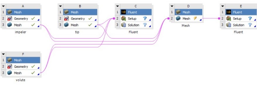
However, while trying to figure out a workaround to save my PC's memory before transitioning to Watertight Meshing, I attempted a "divide and conquer" approach in Workbench. I tried meshing the impeller and the volute casing separately in two different Mesh component blocks, and then linked them both to a single Fluent Setup block (I have attached the Workbench schematic).
Unfortunately, I ran into two major issues with this approach and would love to hear your thoughts on this:
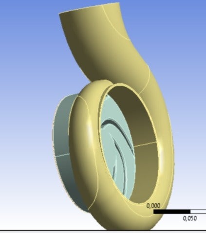
1. Alignment / Coordinate Mismatch When the meshes are assembled in the Setup block, the impeller is completely misplaced and spawns outside of the volute casing (see attached screenshots). How can I correctly align or define the origin coordinates (0,0,0) so they assemble perfectly in their true positions?
2. Best Practice & Interface Accuracy (Shared Topology) By meshing them in separate blocks, I am losing the "Shared Topology" feature, which means I will end up with a non-conformal mesh at the fluid-fluid interface between the rotating impeller domain and the stationary volute domain. For an extreme case like my 1 mm tip clearance, will a non-conformal interface cause severe interpolation errors or divergence? Is this separate meshing workflow actually recommended, or is it mandatory to assemble them in CAD, apply Shared Topology, and mesh them simultaneously in one block?
-
- You must be logged in to reply to this topic.
-
6535
-
1906
-
1463
-
1311
-
1022
© 2026 Copyright ANSYS, Inc. All rights reserved.