Ansys Assistant will be unavailable on the Learning Forum starting January 30. An upgraded version is coming soon. We apologize for any inconvenience and appreciate your patience. Stay tuned for updates.
General Mechanical

General Mechanical

Topics related to Mechanical Enterprise, Motion, Additive Print and more.

2 step model

TAGGED: 

    • isalehinia
      Subscriber

      My student is working on a multi-step structural simulation in ANSYS Mechanical and would appreciate your guidance on the recommended modeling strategy.

      The objective is to simulate a two-stage process:

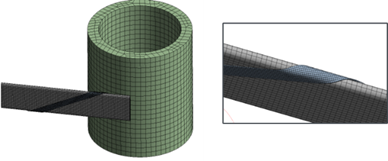
      • Step 1: A very thin sheet (modeled via midsurface/shell representation) is wrapped around a straight core, producing a pre-loaded configuration.

      • Step 2: The resulting wrapped geometry is then bent around a cylindrical support that is not present in Step 1.

      We are attempting to use the Restart Analysis Add-On to transfer the final state of Step 1 into Step 2. The key modeling challenge is introducing the bending cylinder only during the second stage.

      We explored element birth and death to activate the cylinder in later load steps, but this approach leads to convergence difficulties, including under-constrained model warnings and iteration limits.

      Additionally, the model uses remote points (pilot nodes) to drive rotations and constraints across both steps, which further complicates the restart workflow.

      From a best-practice standpoint, could you advise on:

      The recommended way to introduce a body/contact interaction that is inactive in earlier steps but active in later steps within a restart framework?

      Whether element birth/death is appropriate for this type of sequential forming/bending simulation, or if an alternative strategy (e.g., staged contacts, load stepping, multiple analyses, imported deformed geometry, etc.) is preferred?

      Any known considerations when using Restart Analysis together with remote points and shell/midsurface models?

      Do you suggest a different approach to do this model?

    • peteroznewman
      Subscriber

      Please provide images that show geometry of the sheet and what it is wrapped around in step 1 and how it is bent around the cylindrical support and what that looks like for step 2.

      Insert a Contact Step Control so you can have a frictional contact that is needed in Step 2 that is deactivated in Step 1.  You don't necessarily need to restart, you can just solve the two steps sequentially without stopping.

    • isalehinia
      Subscriber

      thanks for the reply, here is an image. The right one shows the core wrapped with a thin sheet, and left shows the cylinder before the wrapped core is bent around it. 

      if I understand it correctly, you mean to keep the cylinder in both steps but in step 1 we should deactivate the contact between cylinder and other parts. Though, we prefer that the cylinder iteself also not be present during the wrapping step, or just be there but not active so that it won't complicate the wrapping process. This is a highly nonlinear problem, so we are trying to simplify it as much as possible.  

    • peteroznewman
      Subscriber

      Thanks for the images. If the contacts between the cylinder and the other bodies is deactivated in step 1, those other bodies will pass through the cylinder like it wasn't there. Visually it will be there, so for a more aesthetically pleasing animation, you can put the cylinder on a translational joint with a displacement joint load and in step 1, move the cylinder a long distance away from the core and ribbon.  In step 2, hold the joint displacement load at a constant value while the wrapping is completed in a few steps, then in the next step, set the joint displacement load back to 0 and the cylinder will return to its original position. In the following step, activate the contacts between the cylinder and the other bodies.

      How are you planning to wrap the ribbon around the core? There are two approaches and #2 is simpler to create in simulation.

      1. Hold the core fixed and move the free end of the ribbon along a conical spiral path.
      2. Fasten one end of the ribbon to the core with the correct spiral angle, put a tension load on the other end of the ribbon along with a lateral and twist constraint and rotate the core to wind it on.
Viewing 3 reply threads
  • You must be logged in to reply to this topic.
[bingo_chatbox]