General Mechanical

General Mechanical

Topics related to Mechanical Enterprise, Motion, Additive Print and more.

Strategy to Displace Compression Only Support

    • ariefyoga.randytama
      Subscriber

      Hello All,

      Im trying to model a simple steel plate with solid elements. It will be used to bridge unmodelled parts. on each end I plan to assign compression only supports. then I want to displace one end of the compression only support by -z direction. I expect the software to turn off the tension supports in the process. How can I do such a thing in Ansys? I see no option to displace supports. Here is the sketch of what I intend to model. Thank you in advance


    • ariefyoga.randytama
      Subscriber

      To add, after the support displacement, there will be vehicle/ wheel load on top of the bridge, Hence the compression support should be able to turn on again if it detects compression. I know that this can be achieved by modelling the contact bodies, but in my case it is taking too long

    • ErKo
      Ansys Employee


      Hi

      No sure I follow, but if you want to turn off the ccompression only support at one load step and then activate at another:

      This is not native inside mechanical – can be perhaps done at own risk using apdl commands, where the compression only support elements are removed in 1st step and brought back in 2nd step (see EKILL, EALIVE).

      (Similar approach to here: https://www.ansystips.com/2017/06/its-ealive-its-alive.html)

      So quite advanced and needs knowledge of APDL (we do have a course on this somewhere) – also the help manual should help to understand apdl commands.


      Perhaps other forum members can help more.

      All the best

      Erik


    • peteroznewman
      Subscriber

      Compression only support is ease-of-use automation that under-the-hood creates a rigid surface and frictionless contact, but the rigid surface can't be moved.

      In your model, keep the Compression only support on the left side but create another body to represent the support for the right side. Create a frictional contact between that new right side body and the underside of the steel plate.  Make the right side body a Rigid body and add a Translational Joint to Ground. Then create a Joint Load, Type=displacement and make the displacement a function of time so that it is held at 0 for 1 second and moved down during step 2 that ends at 2 seconds.

      • ariefyoga.randytama
        Subscriber

        Thank you for the tip. I've tried your suggestion by modelling one of the rigid body. Just like you said, I practically divided the analysis into two steps, step 1 (gravity only) and step 2 (the displaced translational joint to ground).

        The analysis is able to converge in the first step, but it fails in the second as soon as the displacement is introduced. I've defined initial substep of 100, min 1000 and max 1000, turning large deflection on and added damping to the contact. Have you got anymore tips that might help?

        here's the snapshot of the force convergence


        and here is the snapshot of the model and BCs

        heres the result for step 1, it is as expected

        and heres the result of step 2 (unconverged), the shape somewhat make send although it doesnt converge


      • ariefyoga.randytama
        Subscriber

        additional info, In the previous screenshots. I displace the body about 100 units (mm), Ive also tried only displacing it by 5 mm and 10 mm in 1000 (1000min - 1000max) initial substep in step 2. The convergence problem still exists, on top of me refining the target mesh (where I found newton rhapson residuals). On top of that I also added a translational restraint to the corners of the plate that is expected to always touching the target body to (what I suppose) assist convergence.


    • peteroznewman
      Subscriber

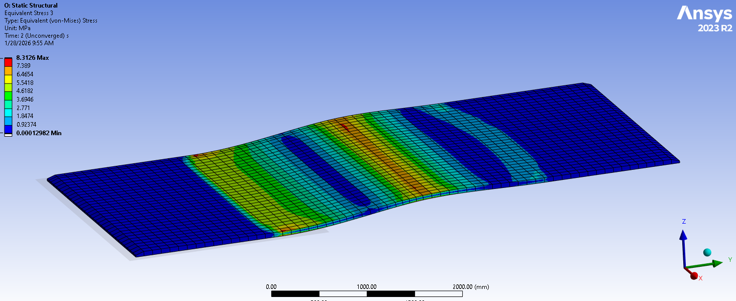
      Good to see some progress.

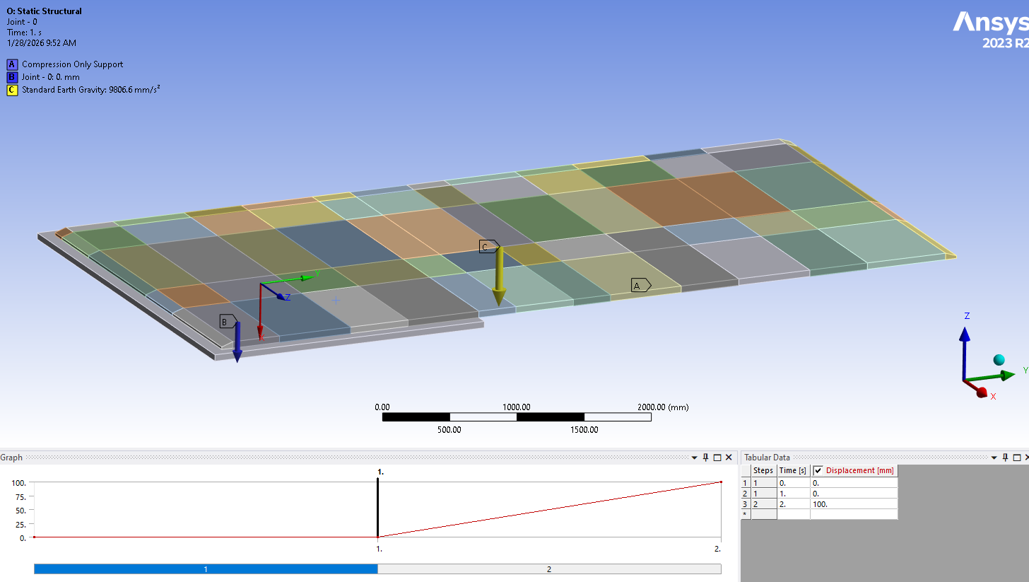
      Next improvement would be to change the compression only support to a rigid surface so you can use frictional contact because friction helps to stablize the convergence and you have more control on the shape of the surface edge and the contact parameters as described below.

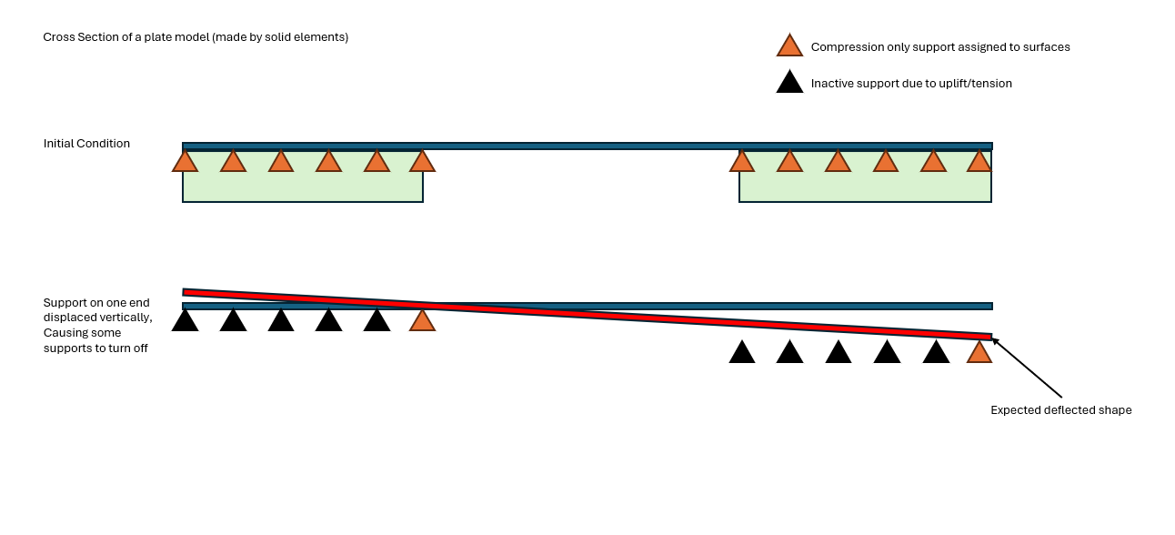
      Add a 90 degree blended arc with a radius larger than the plate element size so that as the plate transitions from making contact with the level support faces to making contact with the edges of the faces as one support lowers, those edges are not a sharp edge but a generous radius so that several nodes are able to touch the tangent point of the radius.  Making the element size smaller at the those edges and on the radius can help.

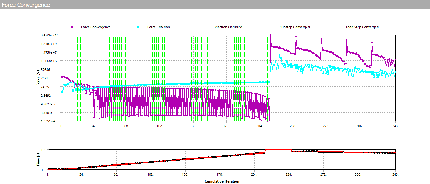
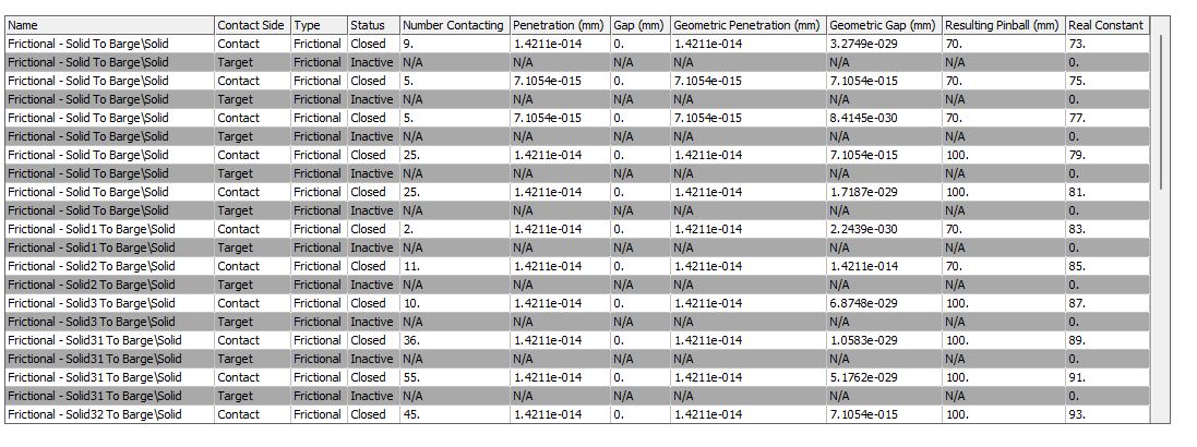
      Change the Frictional contacts at each support by changing the Normal Stiffness Factor and use a number like 0.1 or 0.01 or 0.001.  As the number gets smaller, the more plate nodes will make contact with the blend radius at the edges of the support, but the nodes will penetrate more, so only use a factor small enough to help convergence without getting excessive penetration.

      • ariefyoga.randytama
        Subscriber

        Very nice points and suggestions! I appreciate your help and Ill try it asap. Additionally, I see that the initial contact status between the support body and plate are all closed with very small penetration. will it be better if I have them as near open instead?

Viewing 4 reply threads
  • You must be logged in to reply to this topic.