3D Design

3D Design

Topics related to Ansys Discovery and Ansys SpaceClaim.

Boundary conditions for local shell FEA of a pipe tee beam model-ANSYS transfer

    • rzepakraf
      Subscriber

      Hello everyone,

      I am currently working on a local finite element analysis of a pipe tee and I would appreciate some guidance regarding the correct definition of boundary conditions.

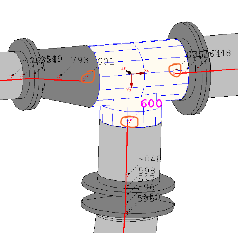
      The global piping system has been analysed in a dedicated piping stress anylising software (based on beam model). It provides nodal results at the tee connections, including:

      • translations (Ux, Uy, Uz),

      • rotations (Rx, Ry, Rz),

      • forces (Fx, Fy, Fz),

      • moments (Mx, My, Mz).

      Below the beam model with marked nodes

      The reason for performing an additional analysis in ANSYS Mechanical is the verification of local stress states in the tee, especially in the branch region. These local stress concentrations are not explicitly resolved in the dedicated software, which relies on beam models and code-based stress intensification factors.

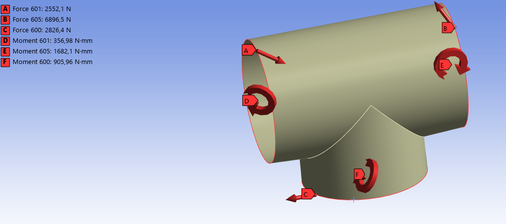
      In ANSYS, I am trying to analyse only the tee itself, using a shell model, without additional straight pipe sections attached. The surrounding piping system is therefore not explicitly modelled, and its influence must be represented through appropriate boundary conditions.

      At this point, I am unsure how to correctly represent the real behaviour of the piping system at the cut boundaries of the tee. I am not sufficiently experienced with ANSYS to be confident that I am defining boundary conditions correctly, especially when the model consists of the tee only.

      In my model, I have applied forces and moments at the characteristic nodes. However, I am not sure how to correctly apply translations and rotations, nor how to properly represent the interface between the tee and the connected pipes.

      My questions is:

      • What is the recommended way to define boundary conditions for a local shell model of a pipe tee when the global system is not included?

      Any advice, practical examples, or references would be very helpful.

      Thank you in advance for your support.

    • peteroznewman
      Subscriber

      The correct way to get detailed stresses on a shell model using results from a beam model is to apply the deformations and rotations of the three nodes from the beam model to three Remote Displacement boundary conditons on the shell model. A Remote Displacement can be scoped to the edge of the shell model and a node will be created at the center of the circle where displacements and rotations can be applied. There are two settings for the Behavior of the connection between the center node and the nodes around the edge of the shell: Deformable or Rigid.  The beam model probably contained an assumption that sections remained planar which would be closer to the Rigid behavior.  If you got output from the beam model closer to where there were flanges being joined, that section is more rigid than a simple pipe wall further away from the flange and closer to the Tee.

      Ansys has a capability where a beam model can represent the entire system, while a shell model of a detailed part of the system can automatically get the deformations and rotations from the beam model to apply to the edges of the shell model using a feature called Substructuring.

      • rzepakraf
        Subscriber

        Thanks for the response peteroznewman. I also found that the best solution for a single component is to apply a Remote Displacement, and I proceeded that way as well. The only drawback of the shell model is that I cannot represent local thickness increases of the component - in that case, it seems to me that a solid body assumption would be the most appropriate.

        1. How do you think I should proceed in the case of a more complex system? Should the model be analyzed up to the nearest support, with constraints applied there and forces and moments applied appropriately at the nodes? Or would it be better to apply Remote Displacements at all connection nodes like fot the tee piece?

        2. The second point is that I would like to automate the data transfer between the programs as much as possible. I was thinking about exporting nodal values from the beam-based program to a .csv file based on coordinates. Then I would like to map the coordinate system appropriately in ANSYS and read in the data.
          In the worst case, even importing just the nodal values as a matrix would already help, and then I could apply the data manually.

        Do you have any experience in this area?

Viewing 1 reply thread
  • You must be logged in to reply to this topic.