Hello,
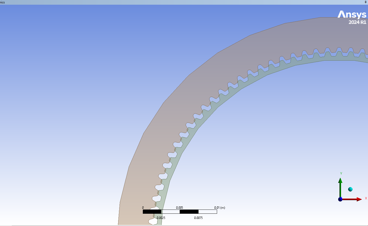
I am currently working on a harmonic drive motion simulation. In my model, the flexspline and circular spline initially interfere when they are coaxially aligned. The interference disappears only when the wave generator is inserted into the flexspline, causing it to deform.
To properly simulate the operation of the harmonic drive, I believe the following sequence is necessary:
First, simulate the deformation process of the flexspline when the wave generator is assembled.
Next, rotate the wave generator and calculate the maximum contact stress in the meshing zone between the flexspline and circular spline.
However, I am facing a problem:
When I include the circular spline in the initial Static Structural analysis (to simulate the fully assembled state), interference occurs between the flexspline and circular spline, leading to solver errors.
If I perform the deformation simulation without the circular spline, it works fine. But in the next step, when I try to assemble the deformed flexspline and circular spline to create a new geometry for the subsequent analysis, I cannot obtain the correct combined geometry.
What would be the best approach to handle this situation?
Should I use a specific workflow or function in ANSYS to correctly assemble the deformed geometry?
Thank you in advance for any guidance.


