TAGGED: #modal-#, ansys, ansys-mechanical, ansys-workbench, modal-analysis, structure
-
-
May 30, 2020 at 11:22 am
shubham99
SubscriberHello This is about a problem which I noticed while doing a modal analysis for finding out natural frequency of the below rollcage in ansys, I observed that for first 6 modes only effective mass participation was observed, also after that there was drastic change in frequency value from 7th mode and effective mass participation became zero.
For the same structure when I fixed suspension points, it gave me values for all the 10 modes and also effective mass participation was observed.
So can you please help me to find out reason for the drastic change in values of frequency and the terms mentioned in ‘Participation Factor Calculation’ table of solution information window. Also should I fix the suspension points for the same analysis and what number of modes I should select. -
May 30, 2020 at 2:23 pm
peteroznewman
SubscriberANSYS staff are not permitted to open attachments. Please use the Insert Image button.
-
May 30, 2020 at 2:52 pm
-
May 30, 2020 at 8:03 pm
shubham99
SubscriberHi peter, I have inserted the images. Let me know whether you are able to see them.
-
May 31, 2020 at 12:29 pm
peteroznewman
SubscriberCase 1 is called "Free-Free" boundary conditions and includes six rigid body motions that have zero frequency. Participation factors are not useful in that case.
Case 2 has non-zero frequencies, so the Participation factors are useful, but be aware, that they depend on how the structure was fixed to ground. You picked many points and used a Fixed connection which drove up the first natural frequency. If instead you created a "kinematic mount" of the frame to ground, you would find a lower first natural frequency. One example of a kinematic mount is for one point to fix displacements in XYZ a second point some distance along Z fixes the displacements in XY and a third point spaced some distance along X to fix displacement in Y. When I say point, I mean a vertex on the geometry, not a face. You can create a virtual point on a face by using Remote Displacement.
-
May 31, 2020 at 12:54 pm
shubham99
SubscriberThanks Peter, but how should I decide number of modes and why was there a sudden increase in frequency for Case 1. Also can you explain the method which you told earlier to fix the body in a bit detail.
-
May 31, 2020 at 1:12 pm
peteroznewman
SubscriberThere are exactly six rigid body modes with zero frequency in a free-free modal analysis. Three translations and three rotations. Whatever the frequency of the first bending mode of the structure is, it might be 10 or 100 Hz, will be what it is, and that will be a big jump from zero. Any non-zero number is a big jump from zero. That is all there is to understand.
The decision on how many nodes to include depends why you are doing the modal analysis.
The kinematic mount I describe above is called a 3-2-1 mount. The instructions I gave were very detailed. What part of it can't you follow?
-
June 1, 2020 at 10:17 am
shubham99
Subscriber
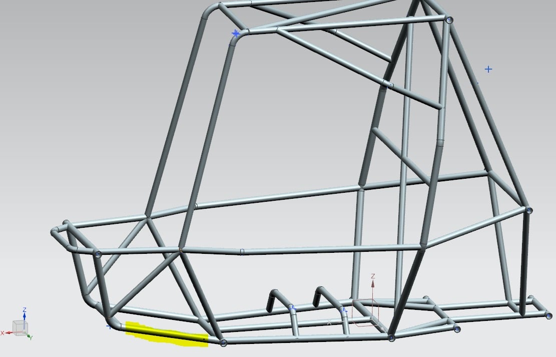
By 3-2-1 kinematic mount you mean that, (*considering for a suspension point member shown below ) I should fix a point(point1) in X,Y,Z, relative to that point traveling in Z axis I should fix a point(point2) in X,Y, then traveling in X axis w.r.t point1 I should fix a point(point3) in Y.[traveling here means a small distance and selection of point was done ]
And for every point I should choose new remote displacement, right? But I was not able to select a point on the face using remote displacement so I choose node selection, moreover this body is circular so while selecting point it won’t be accurate, so is my selection method wrong.Â
Should I carry out the same process for all members on which suspension points are there? OR what step should I follow? And I was asking about how many number of modes I should select, as by default there are 6 modes set in ansys.

-
- The topic ‘Modal analysis’ is closed to new replies.
-
5874
-
1906
-
1420
-
1306
-
1021
© 2026 Copyright ANSYS, Inc. All rights reserved.

