Hi Jasper:
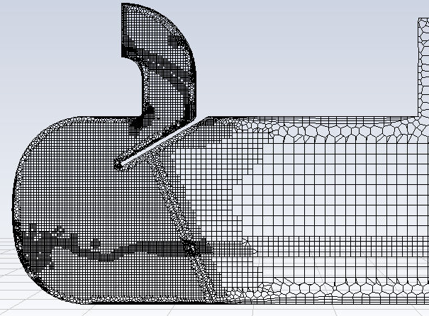
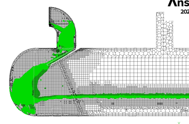
You didn't mention what your refinement criteria are, at what point the manual adaption was done vs. the automatic adaption, or what the green isosurface is, so the question is difficult to answer. To me, the automatic adaption actually looks better, because you at least get some refinement of the VOF stream on the right. Comparing the two images, it almost looks like the manual adaption overrefined on the left side and then just ran out of nodes when it got to the right, leaving you with little refinement there.
If you are using predefined adaption criteria, it is possible that these are not interacting well with your mesh. To set your own adaption criteria, run a solution without refinement and then use this to calculate values for your criteria, ie: typical volume fraction gradient values:
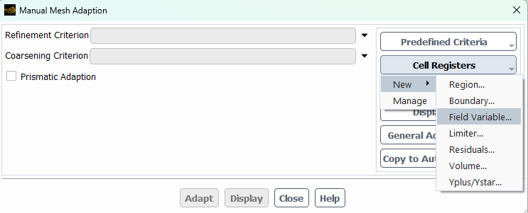
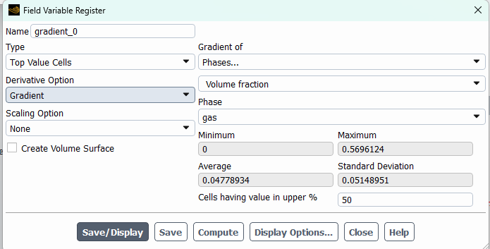
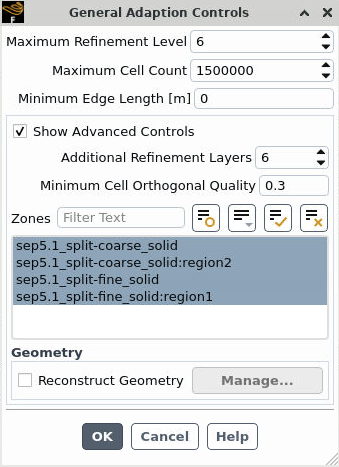
This way of creating adaption criteria allows you to select an appropriate gradient (or other variable) value to trigger adaption and preview cells where the adaption will occur. For instance, you can set your adaption for the top X% of the gradient or variable range that is calculated. I would also specify a minimum cell size in the adaption controls based on what you need to resolve to keep the mesh from getting overly refined in one area and consuming all the nodes.
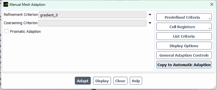
Once you are happy with the setting, copy to automatic adaption to set the frequency:

If you are using a recent release, I would also recommend using PUMA adaption over the legacy hanging node methods.
Regards,
Judy