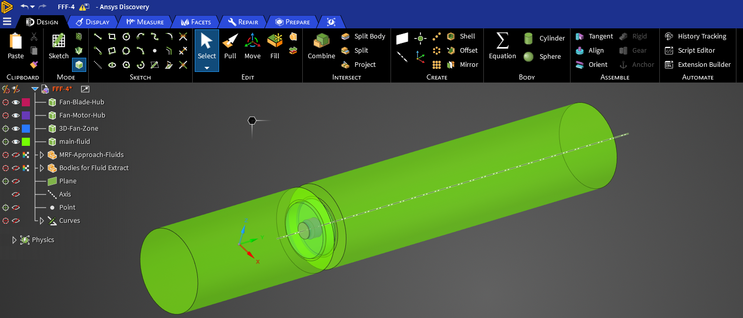
Hello! For my fan simulation, I am trying to implement a 3D fan zone approach. The first image shows a complete view of my model of the main fluid region and the 3D fan zone region embedded inside it. There are also the motor hub and the fan blade hub embedded inside of the 3D fan zone.
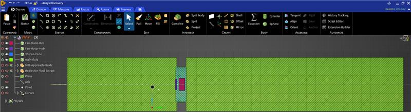
The second picture shows a section view of my model with the main fluid region (in green) and the 3D fan zone (blue). You can also see the 2 cylindrical regions carved out for the fan blades hub (in red) and the motor hub (in purple), and these 2 regions are treated as voids in Fluent. The faces that surround the blades hub and the faces that surround the motor hub are all specified as walls.
Please note that the motor hub deliberately extends into the green fluid region by design and that the 3D fan zone does not completely extend to the top and bottom of the green fluid region by design.

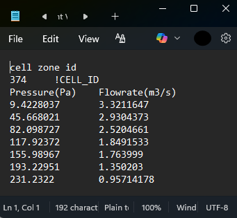
The third image shows the inputs for the 3D fan zone in Fluent for the cell zone (I deliberately specified the initial flow rate to be negative due to the flipped sign convention described below). I have also attached a screen shot of the fan curve document (4th image) that I used as input. This fan curve was obtained using a parametric analysis on an MRF modeling approach (by increasing gage pressure at the outlet for each design point).
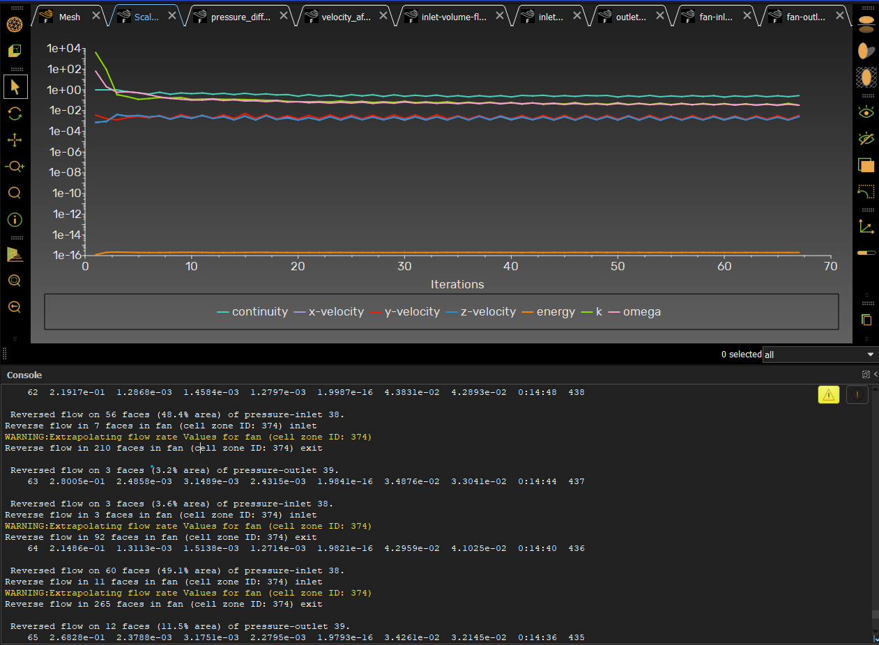
I am facing an issue where the sign convention for the volume flow rate at the inlet and the outlet of the 3D fan zone is flipped. When it is supposed to be positive at the inlet of the 3D fan zone, it is actually negative and that's why Fluent keeps extrapolating the fan curve at every single iteration (as shown in the 5th image). The residuals follow a zig-zag trend every 2 iterations as shown in the image.
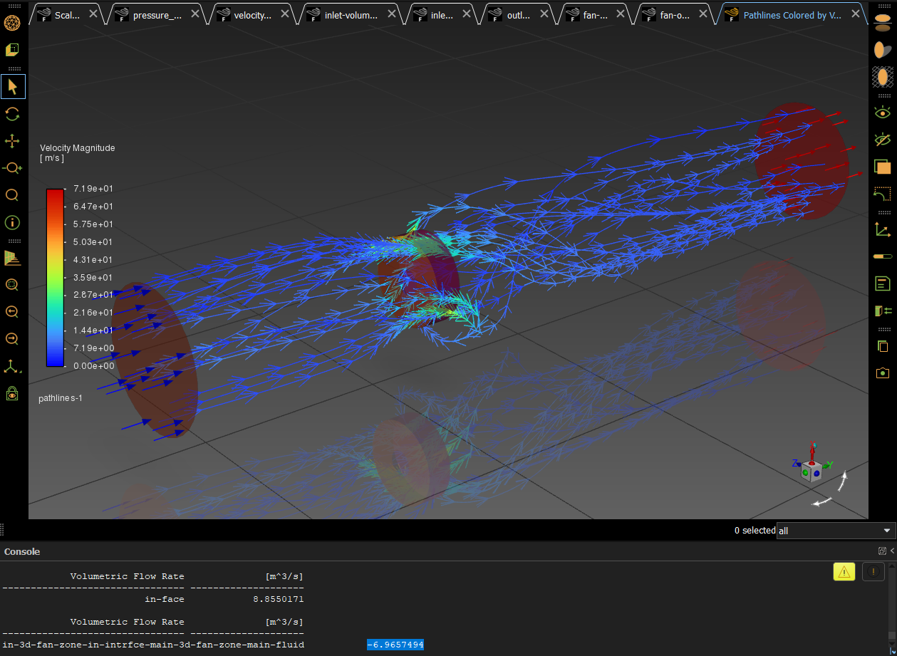
The 6th image shows the volume flow rate at the inlet of the main fluid region (named as 'in-face') to be positive but the volume flow rate at the inlet of the 3D fan zone (named as 'in-3d-fan-zone-in-intrface-main-3d-fan-zone-main-fluid') to be negative (highlighted in blue in the console). The graphics window in this image shows some pathlines with the 3D fan zone moving the flow in the correct direction while also imparting swirling motion onto the flow.
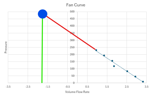
I have attached a 7th picture of the plotted points that were used for the fan curve I provided to Fluent for the 3D fan zone along with a red line showing how they would be extrapolated linearly. For example if the flow rate at the inlet of the 3D fan zone is 1.75 m^3/s, it would mean that the pressure jump the fan should give would be near 150 Pa. But because the sign convention is flipped, Fluent thinks that the volume flow rate at the inlet of the fan zone is actually -1.75 m^3/s (it treats it as negative as shown by the green line) so the extrapolation would give a much higher pressure jump of around 500 Pa (the blue dot in the image).
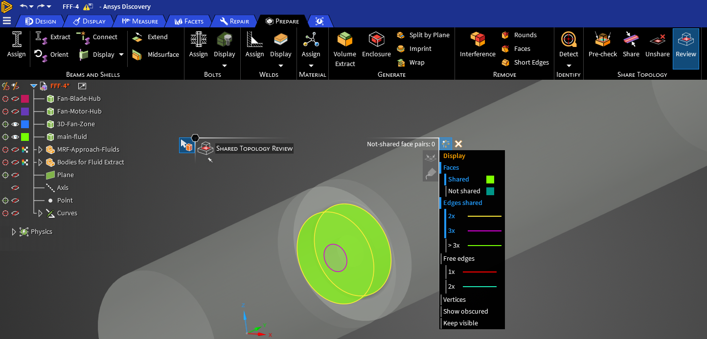
I believe that I am encountering this issue because I performed share topology between the 3D fan zone and the surrounding main fluid region (shown in the 8th image). In doing so, the face normals of the faces of the surrounding fluid region that are adjacent to the faces of the 3D fan zone are used at the shared face. In Discovery, there isn't a way to flip these face normals as the option to flip them is greyed out.
I tried to not share topology between the 3D fan zone and the surrounding fluid region, but this didn't work because I would have to specify the inlet of the 3D fan zone as an interface due to the non-conformal mesh, but Fluent requires it to be specified as an interior face (so the mesh must be conformal and topology must be shared). I also tried to make the flow rate values negative in the provided fan curve text document, but that didn't help either.
The only fix that worked was to cap openings and extract the fluid volume in Fluent itself rather than in Discovery as it prevented the face normal from being overridden on the 3D fan zone inlet (in the case when sharing topology in Discovery between the 3D fan zone and the surrounding fluid volume).
However, I would still like to be able to extract the surrounding fluid volume in Discovery as I personally find it to be more convenient for my model. It also makes the meshing of the surrounding fluid volume a little easier if it is extracted in Discovery first.
After extracting the fluid volume in Discovery, is there a way to reverse the face normal in Fluent itself, or some way to reverse the sign convention so that the volume flow rate at the inlet of the 3D fan zone is positive? I assume that others may have faced similar issues after sharing the topology and would appreciate it if you could provide some guidance on how to fix the sign convention of the volume flow rate at the inlet of the 3D fan zone, thanks!


