-
-
May 18, 2020 at 7:26 am
ltruong
SubscriberHi guys,
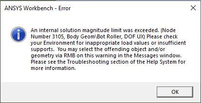
I have an issue with 2D bending that doesn't converge with issues like abrupt change to contact, rigid body motion, internal solution magnitude limit exceeded, etc. Can anyone resolve this issue? Ansys R19.0
I am also unable to mesh rigid bodies so I set them to flexible bodies and use linear materials. Am I approaching this problem the right way?
Regards
ltruong
-
May 18, 2020 at 1:03 pm
Wenlong
Ansys EmployeeHi Itruong,
You can try these few things:
1. Insert a "Contact tool" and check the initial contact status. If there are contact pairs that has a status of "open" or "near open", you can change the interface treatment of that contact to "adjust to touch"
2. Make sure both the upper and the lower equipment parts are also properly constraint.
Regards,
Wenlong
-
May 18, 2020 at 1:19 pm
-
May 18, 2020 at 1:25 pm
Wenlong
Ansys EmployeeHi Itruong,
It is complaining about the bot roller not constrained. Did you have a boundary condition to fix it?
Regards,
Wenlong
-
May 18, 2020 at 4:09 pm
ltruong
SubscriberGreat, I made some progress but was unable to solve it completely.
- Changed the contact behaviour to symmetric (because they are both flexible bodies)
- All contacts have been closed without any issues.
- The only constraint for the top roller was I have set X as 0 so there would not be any lateral movement.
However, what I observed is that the contacts are not being captured along the expected contact line as it can be seen in the photos.
-
May 18, 2020 at 9:18 pm
-
May 19, 2020 at 3:36 am
ltruong
SubscriberI tried your suggestion by setting remote displacements to control the rigid bodies. The solution did not even converge. On the previous post as shown in the photo, I used a flexible body where I was able to mesh the entire body.
Could it be there is an issue with contacts that prevents it from converging the solution any further?
-
May 19, 2020 at 3:39 am
peteroznewman
SubscriberWhy aren't you using symmetry?
-
May 19, 2020 at 5:02 am
-
May 19, 2020 at 12:12 pm
-
May 19, 2020 at 2:09 pm
ltruong
SubscriberThat looks great. Can I ask what you did to repair the geometry? I've been trying to do everything that was mentioned in this thread and the other but have failed.
Ah yes, I have many issues with the ANSYS application. It does not save properly after running the simulations.
-
May 19, 2020 at 6:10 pm
peteroznewman
SubscriberLooking at your animation, your model is working properly. The model has conflicting constraints that are impossible to satisfy. There is a displacement constraint that moves the punch down, and there is a contact constraint. The problem is, the displacement commanded results in a gap less than the thickness (T) of the sheet.
The tip moves down till there is only a gap of T at the centerline. But on the 45 degree side of the die, the gap is 0.707*T which means the contact would have to allow penetration of the plate into the punch and die material. To resolve this conflict, the contact constraint fails and the plate springs back. Just reduce the displacement a little and it will converge without error.
If you replace the displacement with a force, then there would be no conflict. Once the gap on the 45 degree side became T, the punch would stop moving.
-
May 21, 2020 at 10:32 am
ltruong
SubscriberHi @peteroznewman,
Can you please look at the model one more time? I'm confident I have the right files attached this time.
I reduced the displacement but still was not able to get the same result. It looks like you dropped the displacement from -33.2 to -29.05mm.
-
May 21, 2020 at 8:43 pm
peteroznewman
SubscriberOkay, you added plasticity, which requires much more care in setting up the model, much smaller elements, many more substeps, special keyops, etc. I made many changes, which you will be able to see as I attach the modified version below. This is archived without results, so you can't play an animation or make new plots. To do that, you have to Clear Generated Data on the solution and let it Solve again on your computer. I only took it to 24 mm. You can try for more.
-
May 23, 2020 at 6:08 am
ltruong
SubscriberThanks @peteroznewman,
The model looks promising. However, I can't explain the phenomenon at 4 seconds. It seems the sheet metal is attached to the top material and brought it up with the top material. I have attached the animation to show you what I am talking about.
I am now curious to know how to properly model the unloading process because I am observing the springback behaviour and hence plasticity of material. Would adding more steps preceding initial state be sufficient?
Regards,
-
May 23, 2020 at 1:26 pm
peteroznewman
SubscriberThe plate jumps up due to Weak Springs. Under Analysis Settings, Weak Springs are turned on, turn them off.
The material model has plasticity, which produces the permanent deformation. Plot plastic strain and you will see where it is plastic and permanently deformed. At the end of step 3, plot elastic strain. That is the strain that will cause some springback.
-
- The topic ‘Sheet Metal Bending – Static Structural’ is closed to new replies.


-
5059
-
1765
-
1387
-
1248
-
1021

© 2026 Copyright ANSYS, Inc. All rights reserved.


