I'm working on a Maxwell3D transient simulation to calculate the core loss of a large-capacity transformer (80000kVA). The problem is that the avg of the total core loss curve results (after steady) is always much lower (about 25%) than our measurements under the same working condition. It appears that the magnetic flux density in the core limb and yoke is much lower than the working flux density calculated by the theoretical formula, which is weird.
Our simulations considered the anisotropy and nonlinearity of the BH and BP characteristic of the oriented silicon steel. And the model of the core is scaled in the stacking direction to consider the effect of the stacking factor on the effective limb section area. Our previous simulations on small and medium capacity transformers performed excellent agreements on the core loss and limb flux density between model predictions and measurements (or theoretical values). But when it comes to large-capacity products, the simulations with the same modeling method always failed.
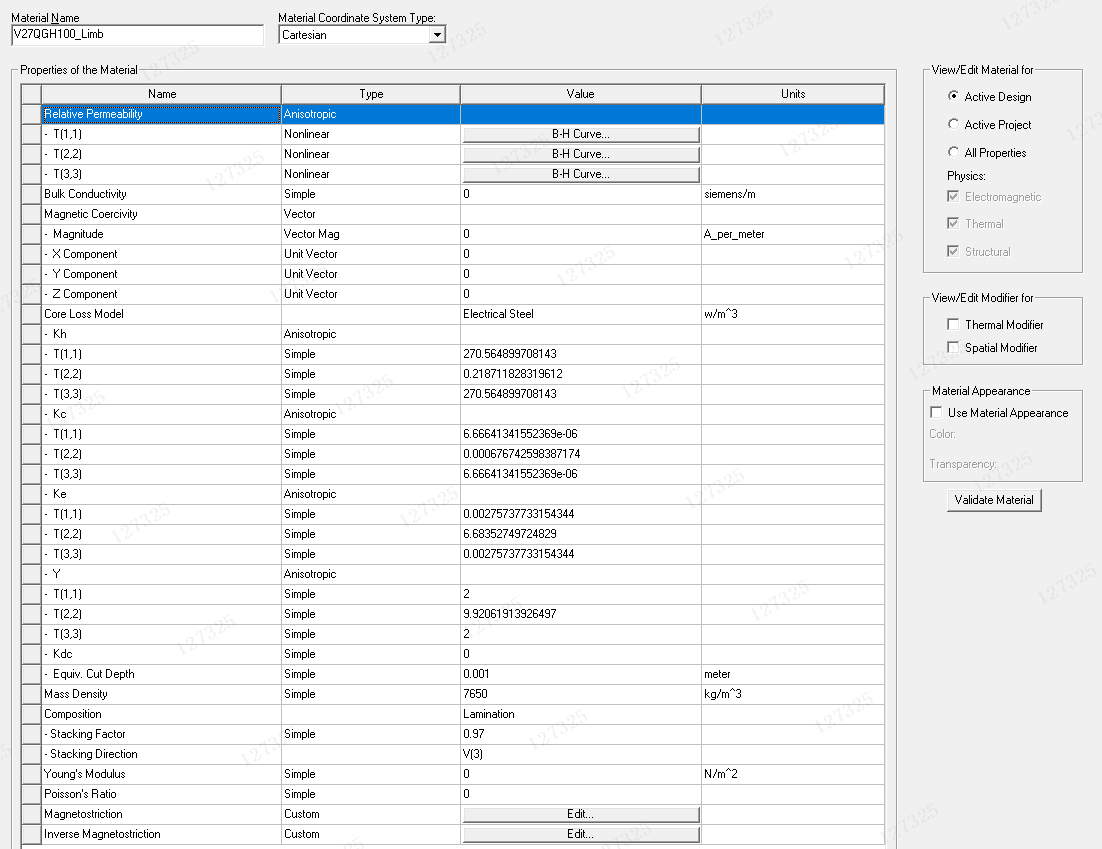
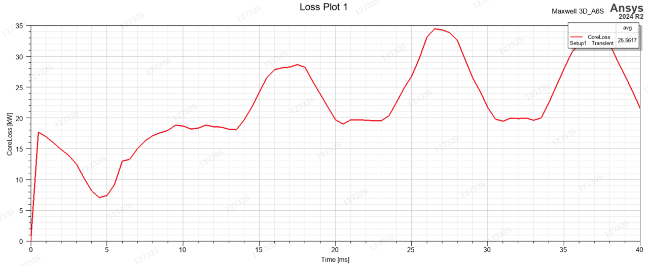
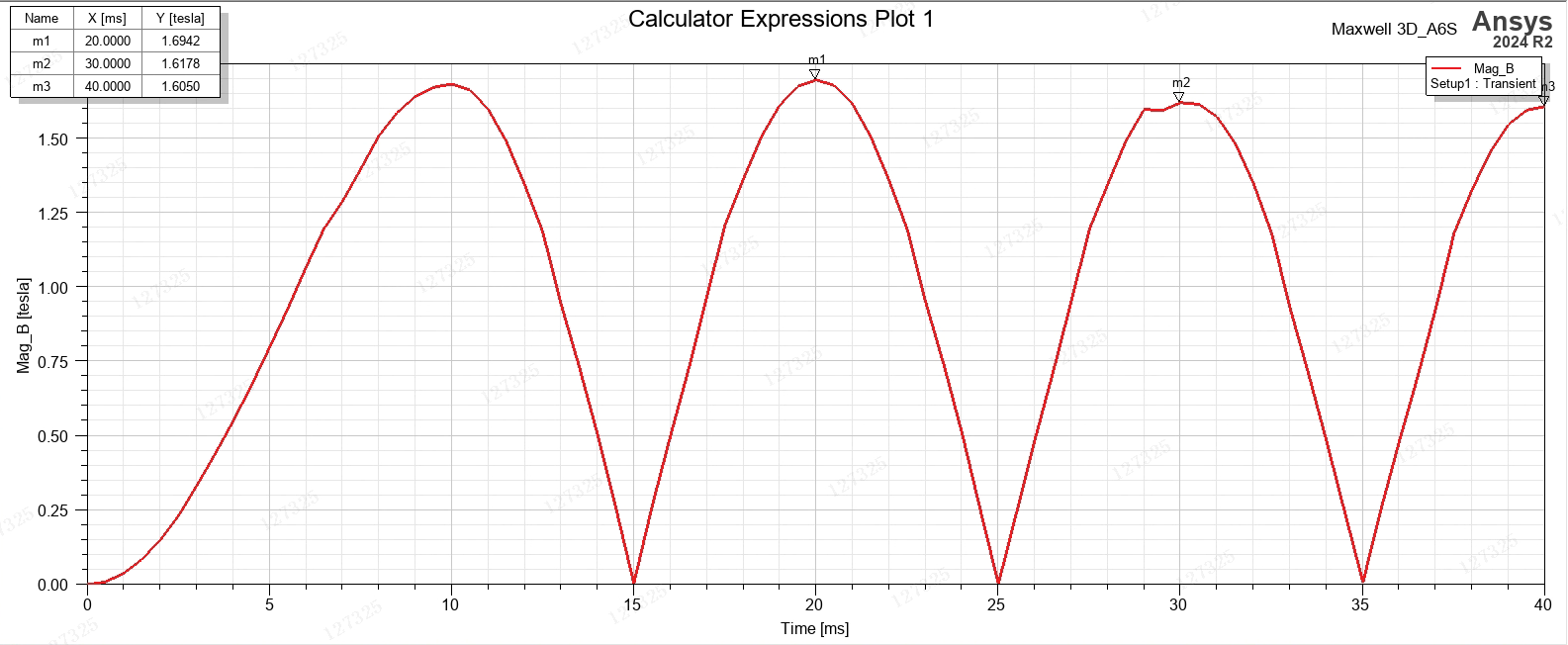
Fig.1 presents the material setting for the core limb. The setting for yoke is reversed along the x and y direction. Fig.2 presents the core loss curve result: the avg between 20ms to 40ms is 25561W, while the measurement under the same working condition is about 32200W. Fig.3 presents the limb flux density (at the center of the A limb): the peak value of the second period is about 1.61T, while according to the theoretical formula, the peak value under that working condition should be 1.7T.