Hello community!
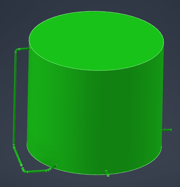
I'm starting a simulation involving the recirculation of water contained in a 3,500 m³ tank, along with the injection of sodium hypochlorite into the discharge pipe. The main objective is to analyze how the hypochlorite concentration inside the tank evolves over time.
The system has three lines:
An inlet corresponding to the tank filling.
An outlet representing consumption or emptying.
A recirculation line, which extracts water from the bottom of the tank and reinjects it through the top, with the injection of hypochlorite into said pipe.
My question is about how to correctly model this recirculation in Fluent. When generating the fluid volume from the 3D model, the recirculation pipe is directly connected to the tank domain, so I cannot assign inlet or outlet boundary conditions to it.
Could you guide me on the best way to realistically represent this recirculation? Any suggestions on how to separate the zones or set boundary conditions would be greatly appreciated.
Thanks in advance!