-
-
June 29, 2025 at 11:29 am
alexandre-antoi.bourrieau
SubscriberHello,ÂI've been trying for several days to simulate the frequency response of the circuit below using ANSYS Circuit.Â
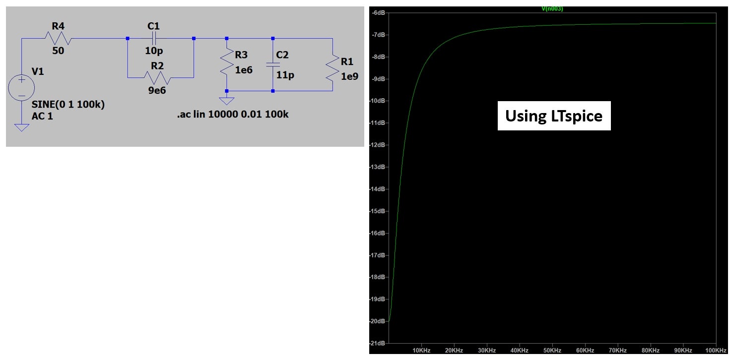
First, here's what I get with LTspice:ÂÂÂ
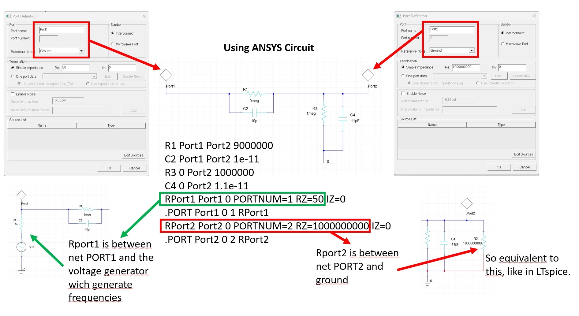
With ANSYS, I have to use ports. For what I understand, but certainely i'm wrong, is when voltage is injected during a LNA, the voltage generator is in serie with the port impedance. If I configure them like this, here is the netlist it gives me. We see in the netlist that port2 impedance is between net PORT2 and ground, like in LTspice.ÂÂ
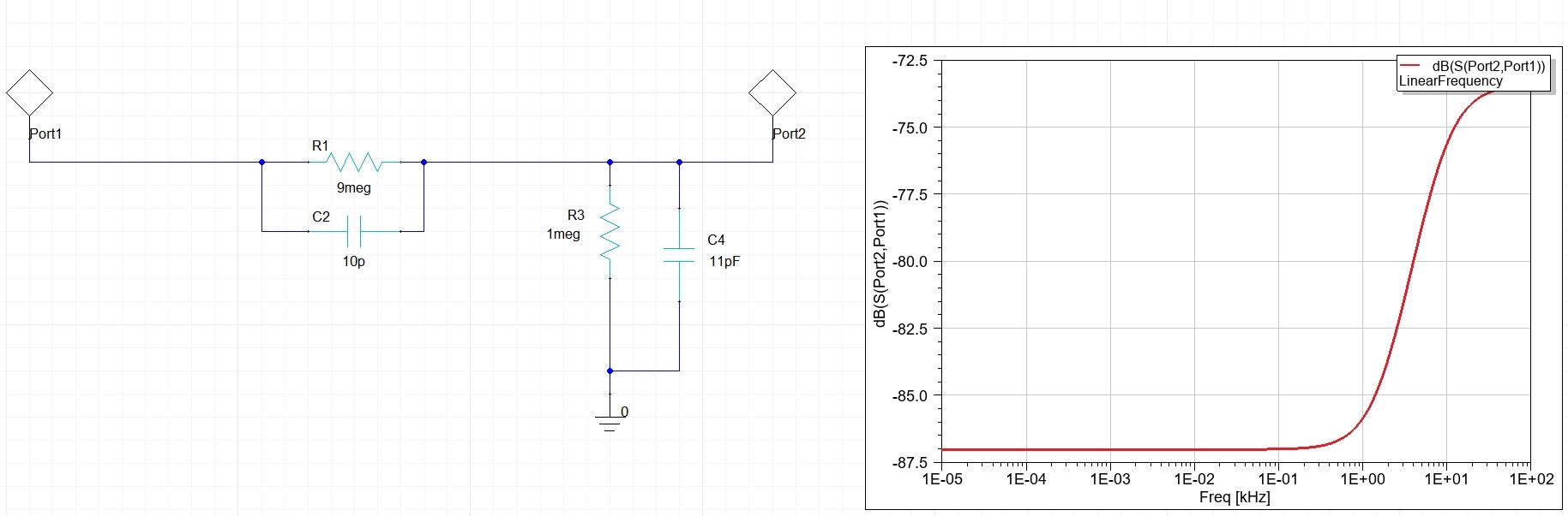
Unfortunately, this doesn't work and I get the following result:ÂÂÂRegarding the netlist, it should work no ?? Can someone explain me what is going wrong ??ÂÂÂ
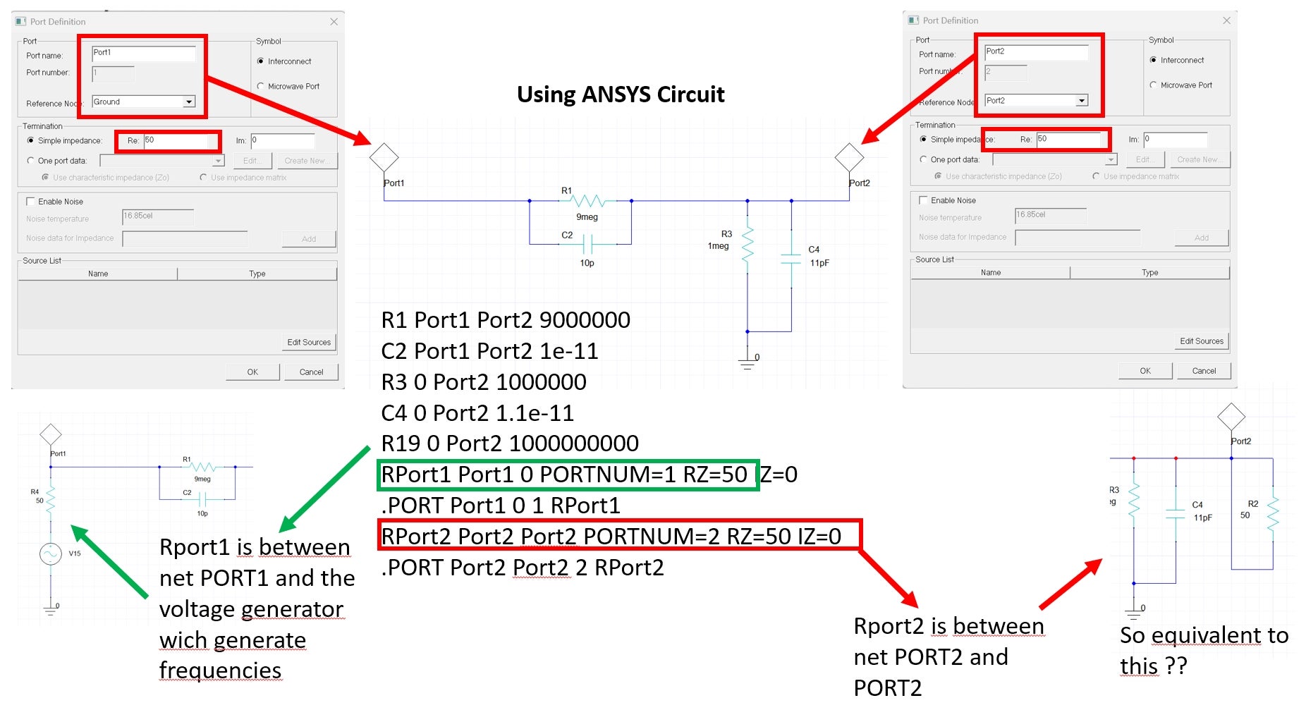
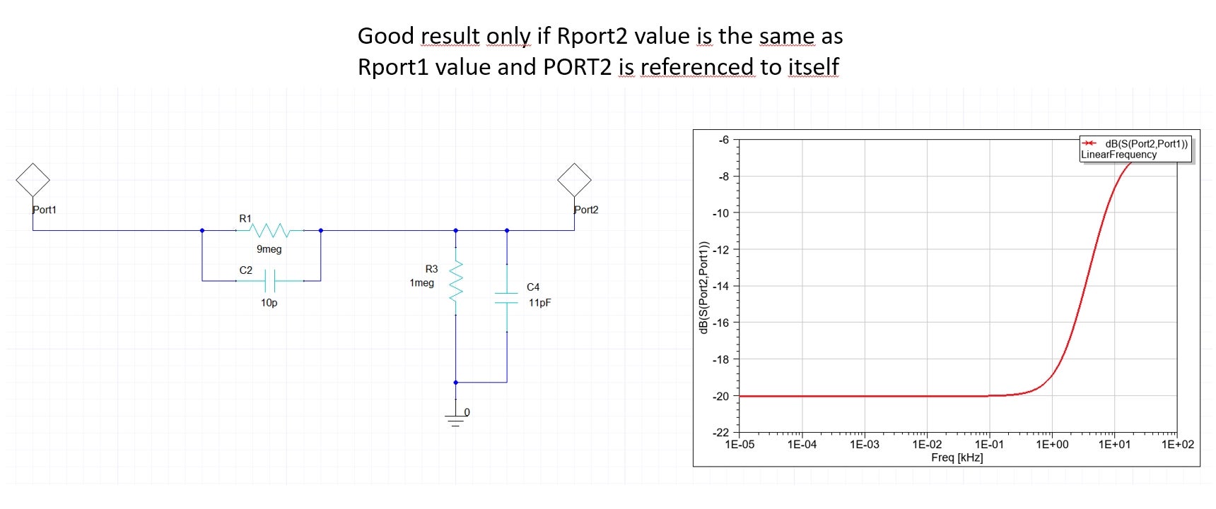
To get the right result, I need to configure port2 with a value of 50 ohm, and referenced to itself. The resistor value need to be the same as the one in port1. For example, if I use Rport1=50, I need to set RPort2=50 to get good result.ÂÂÂWhen looking at the netlist, what I don't understand is why it only work for Rport2=50, because Rport2 is shortcuted regrading the netlist no ?? So any value for Rport2 should work no ???ÂÂÂI think all this is related to S-Parameters I use for tracing Gain Port2/Port1 and both port need to be same impedance to match. Is this the explanation ?ÂÂÂThanks you very much for your help ! -
July 1, 2025 at 6:05 pm
Praneeth
Bbp_moderatorHi,
Thank you for reaching out to the Ansys learning forum.
Please note that you the port configuration is not correct. If you are new to Ansys Circuit, please go through example circuits available through "Open Examples" in the Desktop ribbon area. This folder contains Circuit examples in which low noise circuits and associated documents are avaiable.
Getting started guides are also available through Help menu on the circuits for LNA application.
If interested you can also go through this free video based Ansys Innovation Course on designing circuits - Cosimulation Using Ansys HFSS | Ansys Innovation Courses.
Best regards,
Praneeth,
Click here to join Electronics Community and build a network.
Introducing Ansys Assistant a 24/7 AI-powered virtual assistant for active Ansys academic customers. -
July 1, 2025 at 6:29 pm
alexandre-antoi.bourrieau
SubscriberI have already done all the tutorial
 So if my configuration is not correct please tell me the right way to configure it ?
-
July 3, 2025 at 9:16 pm
Gia
Ansys EmployeeThe port is not a voltage source.
Change the 'symbol' from 'Interconnect' to 'Microwave Port'. - This only changes the symbol, but provides a more intuitive understanding of how the port is defined.
A 'port' is like the connection to a physical Vector Network Analyzer (VNA). - The port terminates the node it is connecting with a 50 ohm impedance to ground - while allowing us to view the S-Parameters.
Linear Network Analysis in Ansys Circuit is used to compute S-Parameters (ratio of incident & reflected voltages) - which is a different type of analysis than small-signal AC bode plot (Vout/Vin).
When trying to use Ansys Circuit LNA analysis for your circuit, the 50 ohm impedance of the ports will load down those nodes and thus modify the response you see compared to LTSpice.
This is becasue LT Spice uses high-impedance measurement ports/probes for determining the frequency response for the isolated lumped circuitdefined in your schematic.
So, if your goal is to create bode plots for lumped circuits, you should use LTSpice. - Ansys Circuit is not the correct tool for this purpose.
Â
-
- You must be logged in to reply to this topic.
-
3492
-
1057
-
1051
-
965
-
942
© 2025 Copyright ANSYS, Inc. All rights reserved.