TAGGED: ansys-apdl, ansys-contact, apdl, Contact Method
-
-
June 25, 2025 at 7:29 pm
vighnesh.nandavar
SubscriberI am performing a contact analysis of a small plunger pressing against a 10mm plate (have simplified my model to a 10mm square bar for now) and I am not defining any force, rather giving displacement to the plunger to touch the plate.
After my analysis, the plunger goes direct inside the plate defying the contact inputs.
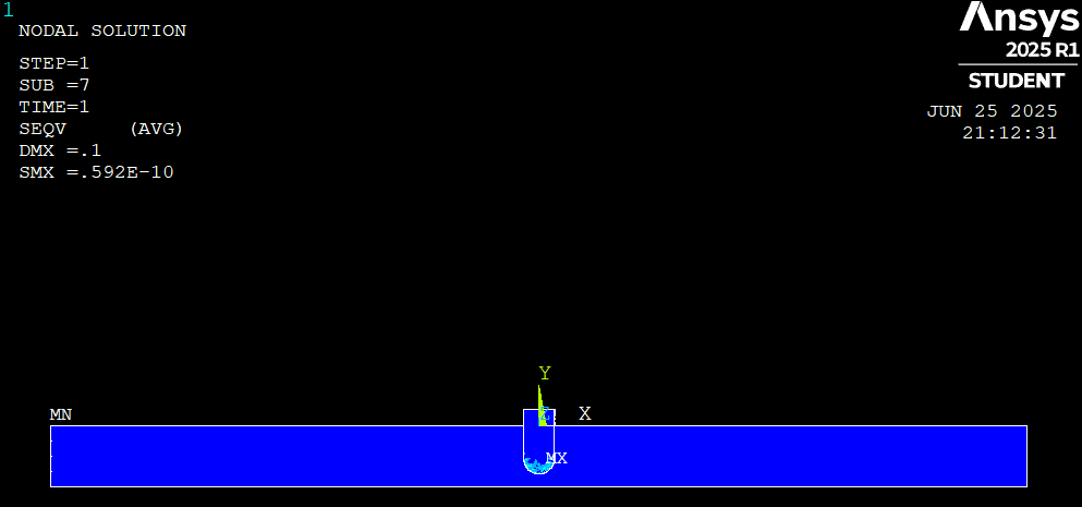
There is a gap 0f 0.1mm between two bodies. For the plunger , I have given displacement in Y as -0.1 on the nodes present on the top most surface of the plunger.
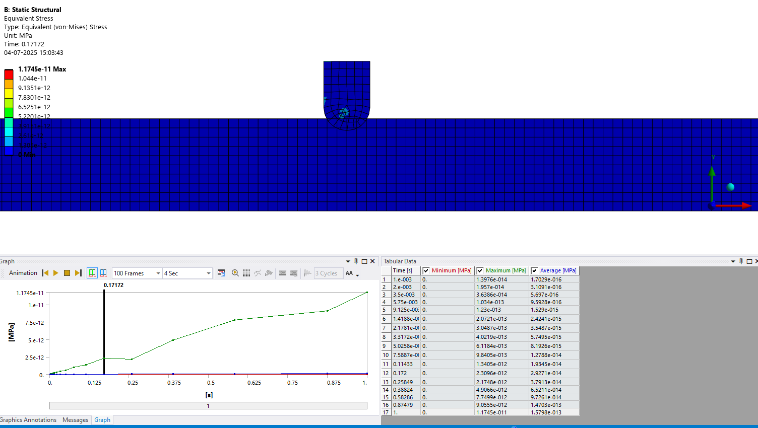
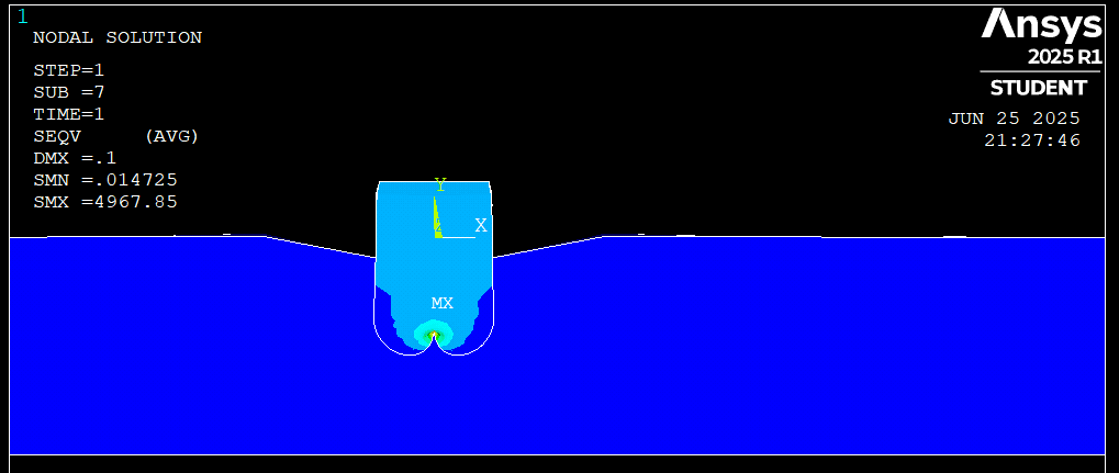
What more ?! I am super confused why the plunger is displacing roughly 8mm down.
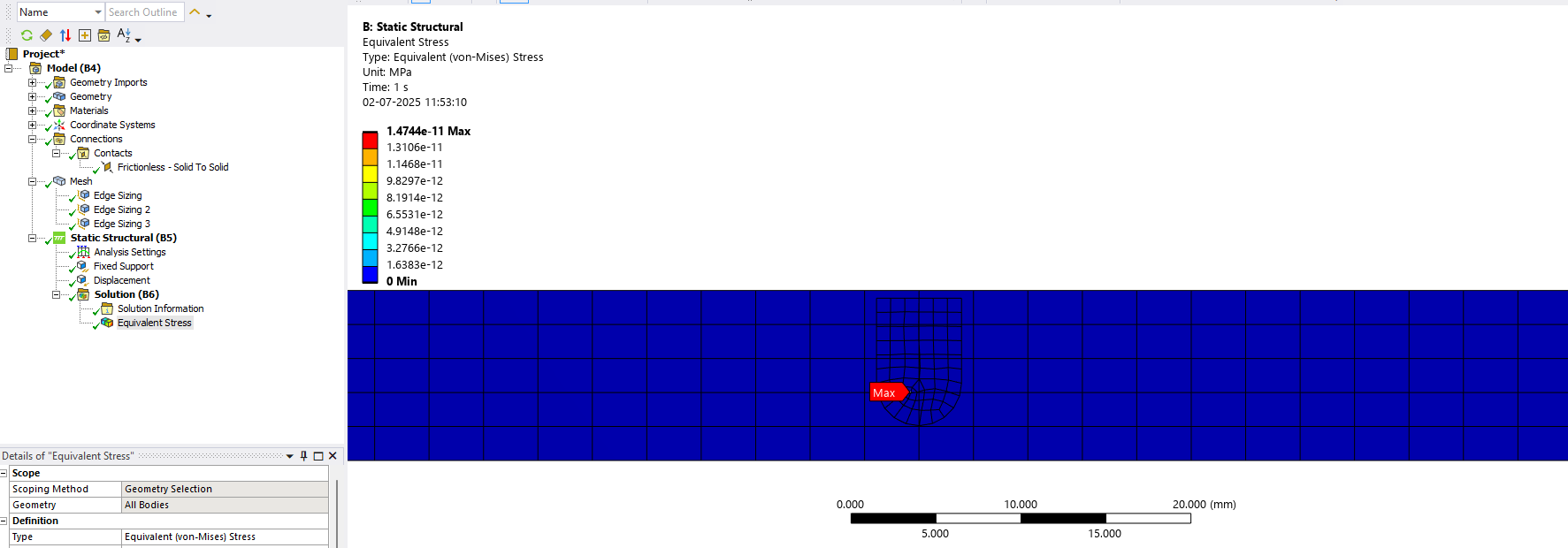
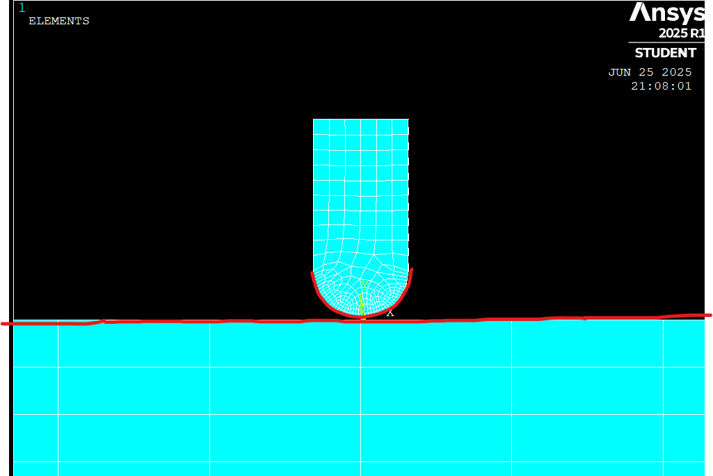
The following are the contact details I have given:
The image indicates red lines. Those are the contact and target surfaces. Well, I have chosen the nodes on these surfaces. I have chosen the contact algorithm to be Augmented Lagrange since its a combo of Penalty and Lagrange. For contact detection, "On nodes-Surface project" because I would like to cast the nodes on to the surface. I have not given any initial penetration since there is a fixed gap of 0.1mm between both bodies. Also the friction coeff for both are 0.
My guess is that I have made a mistake in chosing the contact parameters.
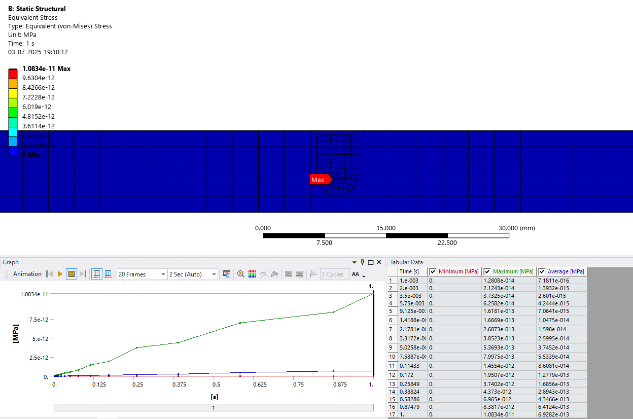
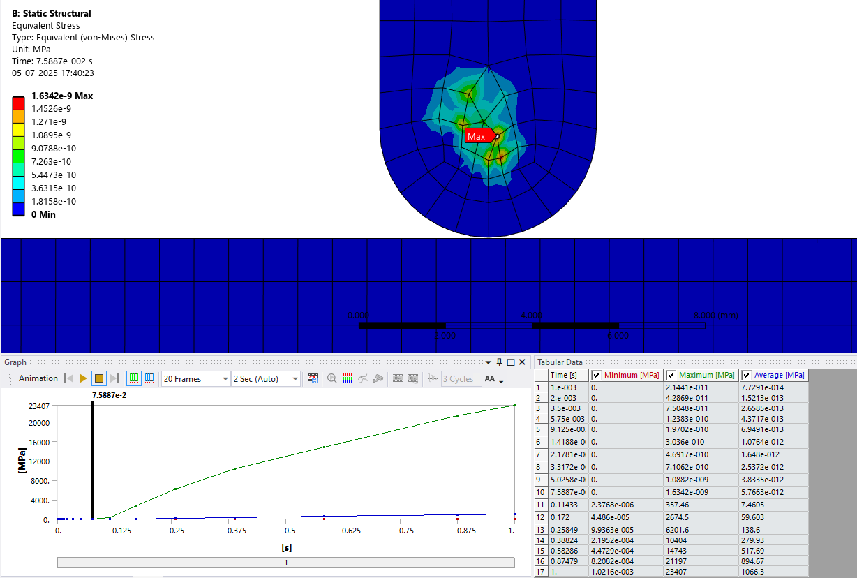
One more, when I try to give a contact offset of 0.1, the following thing happens which I wonder why
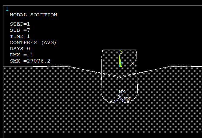
Insights on this much appreciated :) -
June 26, 2025 at 1:49 pm
Erik Kostson
Ansys EmployeeÂ
Â
Hi
Â
See our help manual where there are many apdl examples related to contacts analysis.
https://ansyshelp.ansys.com/public/account/secured?returnurl=/Views/Secured/corp/v251/en/ans_vm/Hlp_V_CH1_IDXELEMNUM.html
Â
See also the help manual for the traget and contact element settings.
Â
Finally use many substeps (NSUBST) so contact can be detected and to aid convergence.
(NLGEOM,ON also)
Â
If you would like to model this in Mechanical workbench, then see our free courses in contact analysis using WB mechanical.
Â
See the VM apdl examples we have that are similar.
Â
All the best
Â
Erik
Â
Â
Â
-
June 26, 2025 at 7:10 pm
vighnesh.nandavar
SubscriberHi Eric,
Thank you for the information bundle. Let me go through it and get back with an update on this thread.
-
July 2, 2025 at 9:59 am
vighnesh.nandavar
SubscriberHi Eric,
I went through the link you shared. Unfortunately, it confused me a bit more. So I went through the ansys innovation videos on youtube for contact analysis.
I thought of solving the same probem in Workbench. I did so. But here is the result of it. I have given steel to be the material for both the bodies.
Â
I have given a displacement of -0.1mm in the Y direction.
What I am not at all able to understand is that why is the plunger travelling roughly 8mm downwards ?
Â
-
-
June 27, 2025 at 4:56 am
mjmiddle
Ansys EmployeeAdding my two cents:
- Contacts work best with similar element sizes on both sides. While the target side can have larger elements in some setups, such as sliding, your "target" elements are many times the size of the elements on the plunger side, which I assume is your "contact" side. If not, it should be.
- As Erik Kostson wrote, you will need small time steps. You need to make sure time steps are small enough to capture the instant of contact within the pinball radius to detect contact. You may think just increasing the pinball radius woud allow this with larger time steps, and it can help a little, but it's most important to use a small time step to get that contact instant. Using a large pinball radius can have some strange effects such as contact occuring and bodies deforming while a gap is mainatined between bodies. Also, you wrote that you set a contact offset of 0.1, and this model does not look appropriate for any offset prescribed.
-
July 2, 2025 at 11:29 pm
mjmiddle
Ansys EmployeeÂ
The plunger is most likely intersecting because your time steps are too large, so it misses the time of impact. You can set the time stepping in the Analysis Settings.
Â
-
July 3, 2025 at 8:16 am
-
-
July 3, 2025 at 8:43 am
mjmiddle
Ansys EmployeeLoadsteps are 1 second by default so a 1 second time for substep is very large. In fact, it means just one substep for the entire loadstep. Try initial substeps of 50 or 100. If that doesn't work, try 1000. 1000 substeps within a 1 second load step means 0.001 second for each substep or just the initial time step if you set 1000 for initial substeps.
You can let it be free to make smaller time steps when necessary by setting an even smaller minimum time step. Using substep specification, as your image shows, you could do this by setting the maximum substeps to something like 1e4 or 1e5.
-
July 3, 2025 at 5:10 pm
-
-
July 4, 2025 at 4:52 am
mjmiddle
Ansys EmployeeMaximum substeps of 1e7 is a little high. You could be waiting forever for a solution just to find it didn't go right. You are alwasy free to press the interrupt or abort button.
I see that your elements are still not similar sizes on contact and target sides as previously advised. Also, since you have 17 converged substeps, you could play an animation or select a row and right click to "retrive this result" to see if there was any time it was in contact. By the slope of the graph at the beginning, it doesn't look like it ever contacted to me, but it may have in the first few substeps, which are pretty small.
Also, as previously explained, make sure "contact" side is the plunger side and "target" side is the flat surface.
-
July 4, 2025 at 1:11 pm
vighnesh.nandavar
SubscriberÂ
Hi,
Actually I too thought that the solution would take forever when you mentioned 1e5. But also with 1e7, it takes just around 10sec to finish computing.
I have tried to a get a close match to the element sizes for the contact and target bodies and yes, the bodies are rightly chosen. I just cross verified them.
When I run the animation, the slope at 0.1712s shows a small change in the colour contour. However that is mostly indicating that the value if stress is slightly higher. Even when I look at the slope, there isn’t a dip that is helping me conclude there might be a contact (let me know if my thoughts are wrong here). By the end of the analysis, the plunger stays inside as in previous.Â
Isn't displacement supposed to work like how we suggest? Shouldn't it just travel -0.1mm and perform calculations for this samll distance ? Why would it sink all the way down ?Â
-
-
July 5, 2025 at 1:25 am
mjmiddle
Ansys EmployeeSorry, somehow I missed it was stress you were showing, not deformation. Those low stress numbers are just noise.
If you intended the displacement load to be less, then maybe your result images are showing a scaled result. If not, then you must not be aware of the size of your model or the units.
Try setting a contact pinball radius so the diameter is a bit bigger than the contact element size. Try setting a normal stiffness factor of 0.1.
-
July 5, 2025 at 4:02 pm
vighnesh.nandavar
SubscriberHi,Â
My element size is 0.8mm. I now tried with 1mm pinball radius, 1.5mm radius and also auto detection.
I now have new things that surprises me.
Firstly, you are right, I did not notice the result's scale. I made it to True Scale now. The plunger thankfully doesnt pierce in now. Also played with the stiffness value. The computer decided value yields the stress as shown in the screenshot while with the normal stiffness factor of 0.1, it gives a value of 23126MPa at t=1s
However, if you look at the screenshot below, there is still that 0.1mm gap. So I tried increasing my displacement to -1mm. Well, the gap still stays the same.
Why does this happen ?
Also, if you look at the table for stress now, it shows a maximum of 23407MPa. The legend on the screen displays 1.63e-9 though. Now this confuses me.If you also look at the region of stress, it is not on the edge rather a bit higher. I am surely wondering why. I first thought it is may be because of a larger pinball radius. When I used the auto detect option, the radius was much smaller. So I could rule out that.
-
-
- You must be logged in to reply to this topic.
-
3407
-
1057
-
1051
-
896
-
882
© 2025 Copyright ANSYS, Inc. All rights reserved.