Ansys Assistant will be unavailable on the Learning Forum starting January 30. An upgraded version is coming soon. We apologize for any inconvenience and appreciate your patience. Stay tuned for updates.
General Mechanical

General Mechanical

Topics related to Mechanical Enterprise, Motion, Additive Print and more.

How to properly set up a bushing joint?

    • siyangli1998
      Subscriber

      Hi everyone,

      Does anyone know how to properly set up a bushing joint?

      Here is my scenario (see figure): I want to place bushing joints between Arm1 and Arm2, and between Arm2 and Arm3. Arm1 is fixed to the ground.

      My goal is to apply forces at different angles to the right end of Arm3, and then measure the resulting deformations in all six directions (X, Y, Z, Rx, Ry, Rz) at each joint.

      However, the software keeps giving me an "underconstrained" or "Due to constraints, the solver failed to converge on the nonlinear problem. "error.
      What should I do to solve this issue?

      Thanks in advance!

    • peteroznewman
      Subscriber

      You haven’t said if Arm 1, Arm 2 and Arm 3 are rigid bodies or flexible bodies. 

      If the arms are flexible bodies and you connect them with rigid Fixed Joints, you can apply a force to the end of Arm 3 and track the motion of the two rigid Fixed Joints in X,Y,Z,Rx,Ry,Rz due to deformation in the arms.  Such a model will have no issue with being underconstrained.

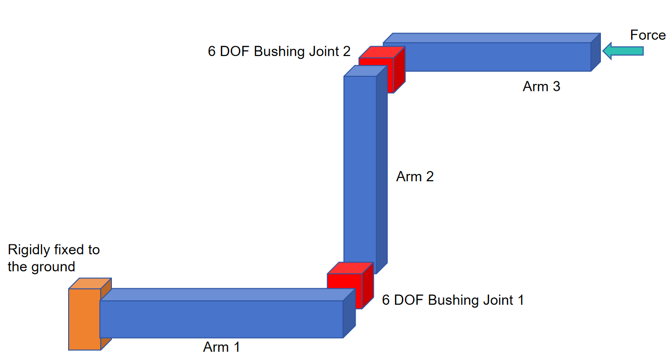
      If the arms are rigid bodies, you must have a Bushing Joint between the arms in order to have some displacement caused by the applied force. A bushing joint provides six non-zero stiffness values in the translation and rotation directions.

      You can also have flexible arms connected with Bushing Joints.

      Here is a good article on Joints by Steve Kiefer that explains how to create a bushing joint.

      https://steve-kiefer.medium.com/ansys-mechanical-all-about-joints-173f1fa40e15

Viewing 1 reply thread
  • You must be logged in to reply to this topic.
[bingo_chatbox]