-
-
June 20, 2025 at 11:01 am
seealtaf
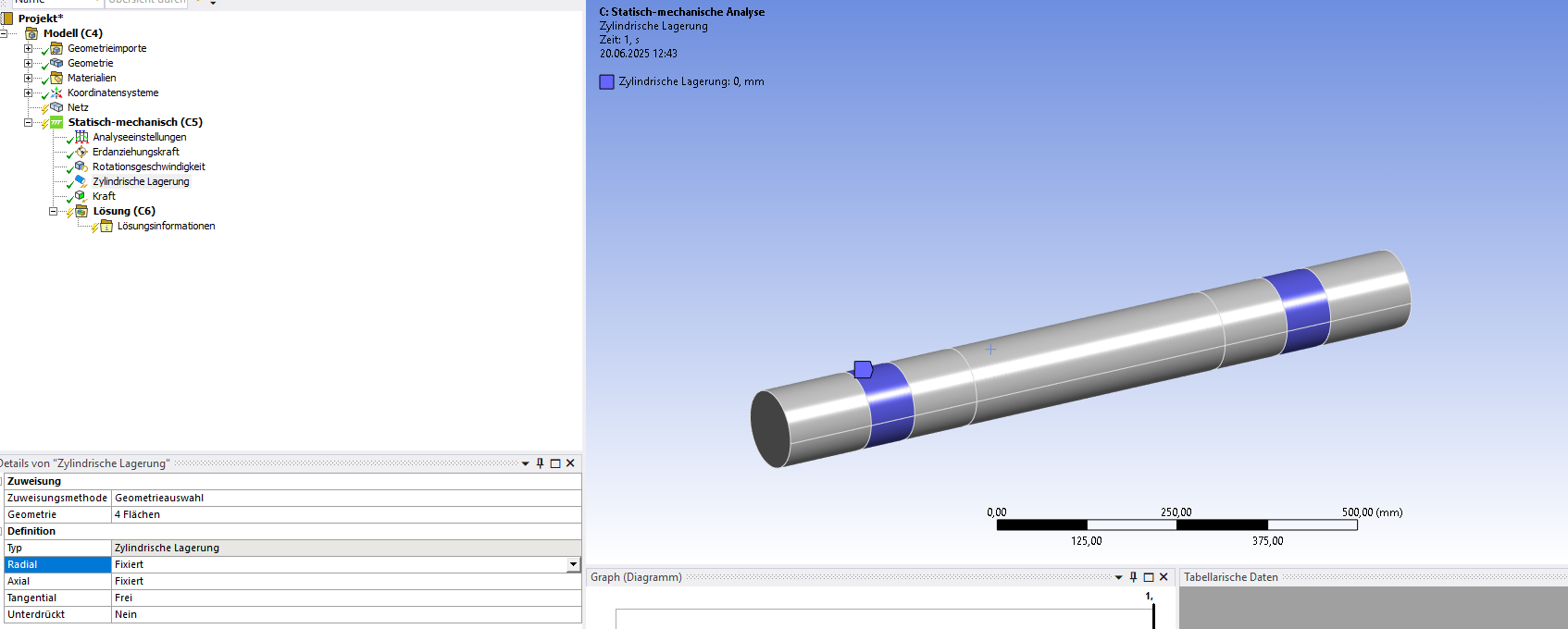
SubscriberI want to support the shaft on 2 Load bearings on either end as shown in the image. I gave a cylinderical support with Tangential free and Radial-and-Axial fixed. I then gave a centre load and Rotational speed. Is this right or should I give some other kind of support?
When I solve, it gives an error that it isn't supported sufficiently to avoid a body movement. Thanks for your time.
-
June 20, 2025 at 2:38 pm
SaiD
Ansys EmployeeHello! Based on your description, if the tangential DOF is free for the cylindrical support and you apply a rotational velocity, the shaft would undergo a rigid body rotation about its axis. Static Structural analysis does not deal with rigid body motion and that is probably the reason why you get the error about the model not being constrained sufficiently.
What physical scenario are you trying to simulate? Could you describe the loads and boundary conditions you are applying? -
June 20, 2025 at 2:49 pm
seealtaf
Subscriberoh.. so This is a shaft on which a fan is mounted. between the bearings in the center. And one end of shaft is flanged connection to a motor. I gave a central mass distributed on the central surface of 3000kg and a rotational speed about X axis of 1125 rpm. So for the boundary conditions I gave a cylinderical support with Tangential free and Radial-and-Axial fixed, which would mean the Rotation about X axis is free to rotate, right? I think I should also give an External displacement of 0mm and 0° at the flanged end of the shaft?
-
June 20, 2025 at 3:28 pm
SaiD
Ansys EmployeeActually, part of what I wrote previously is not entirely accurate. The "Rotational Velocity" boundary condition in a Static Structural analysis mainly accounts for the "structural effects" of a part spinning at a constant rate. You can find more information here: 17.6.1.3. Rotational Velocity
The part about the model not being sufficiently constrained due to the applied boundary conditions still holds true (i.e. the error is due to insufficient constraint on rotation about x-axis). Since axial and radial DOF are 0 for the cylindrical support, the rigid body displacements in all 3 directions have been constrained. Rigid body rotations about y and z axes are also constrained due to radial DOF being 0 at the two highlighted location. You only need to figure out how to constrain rigid body rotation about x-axis. One way would be to use Remote Displacement on the flanged end of the shaft and define Rotation X to be 0 and leave all other DOFs free (to avoid overconstraint).Hope this helps.
-
July 4, 2025 at 8:20 am
altaf.bankotkar
Subscriberok this gives a result. But I just want to understand that the shaft still rotates at 1250rpm right? Even though Rotation at X is given as 0°?
-
- You must be logged in to reply to this topic.


-
4989
-
1665
-
1386
-
1242
-
1021

© 2026 Copyright ANSYS, Inc. All rights reserved.


