We’re putting the final touches on our new badges platform. Badge issuance remains temporarily paused, but all completions are being recorded and will be fulfilled once the platform is live. Thank you for your patience.
General Mechanical

General Mechanical

Topics related to Mechanical Enterprise, Motion, Additive Print and more.

Contact Forces not making sense (to me at least)

    • lvelasquez
      Subscriber

      Hello,

      I´m doing a static simulation in a rack, where the load of 10,000N is applied on three faces, like this:

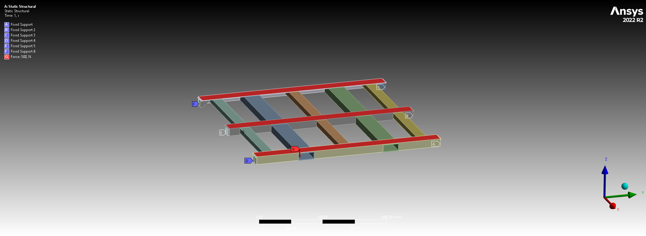
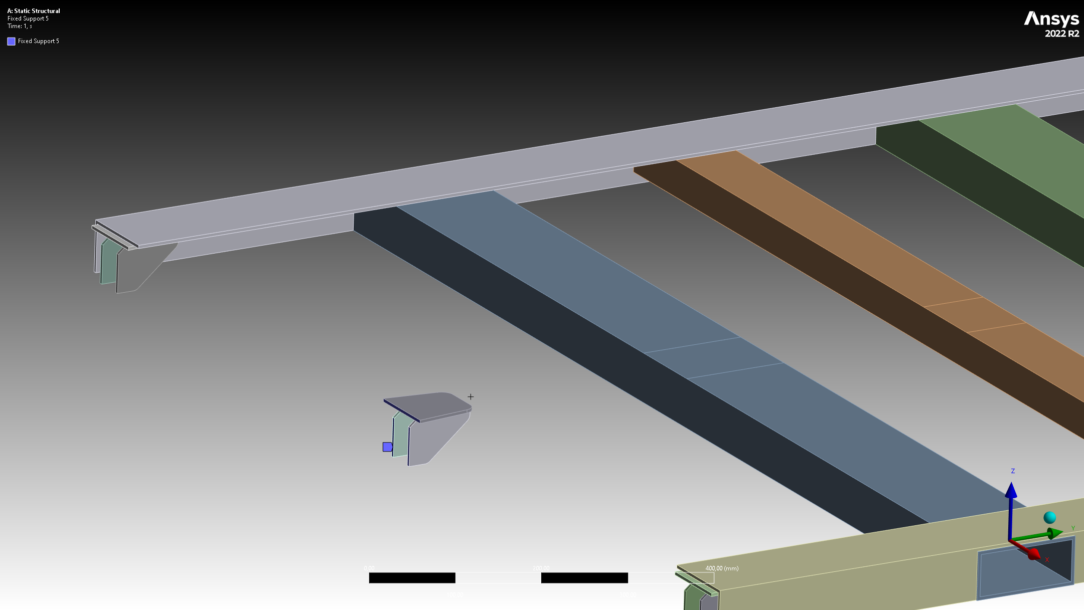
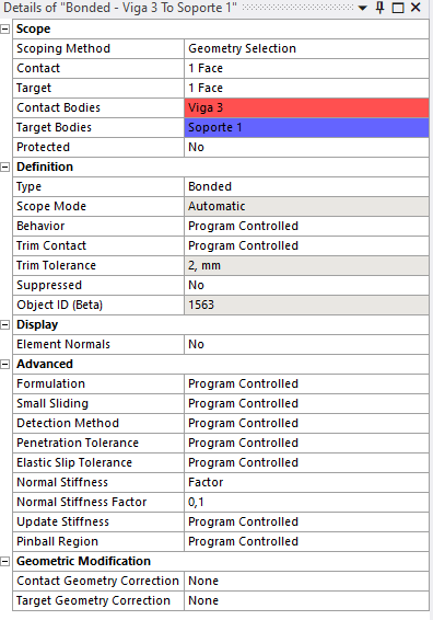
      In six points there should be a column holding everything together but I used fixed supports, just for simplicity (the whole structure is composed of 4 levels, with the same geometry). Everything will be weld together so I used bonded contacts.

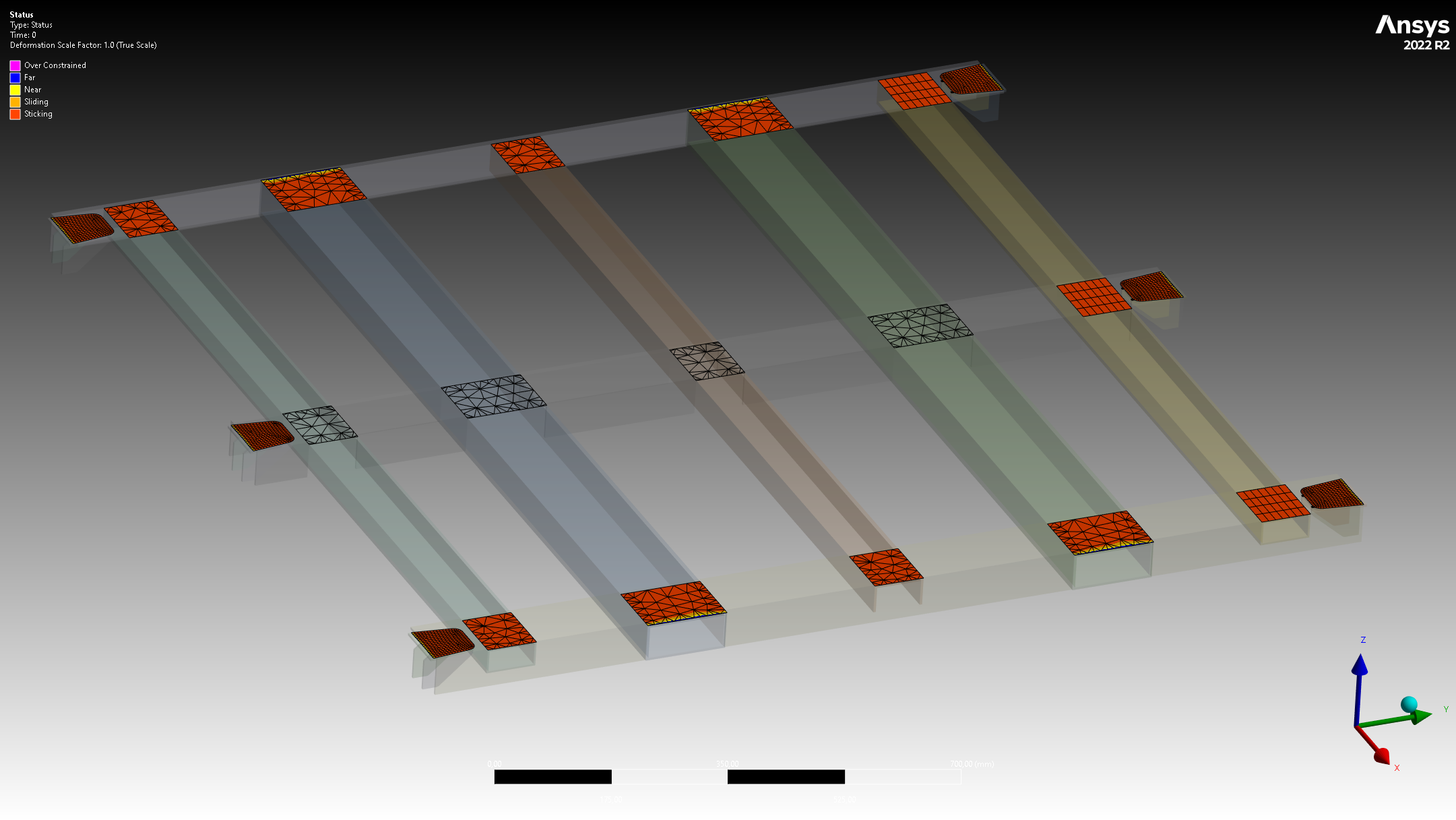
      Now, when I want to check the force reaction in the contact area there are some odd things that I can´t seem to understand:

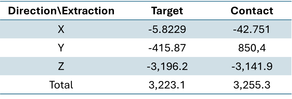
      The force when extracted from either the Target or Contact have the same direction; the Y component is the only opposite but twice the value. The rest of the contacts do have opposite directions, not exactly the same components though.

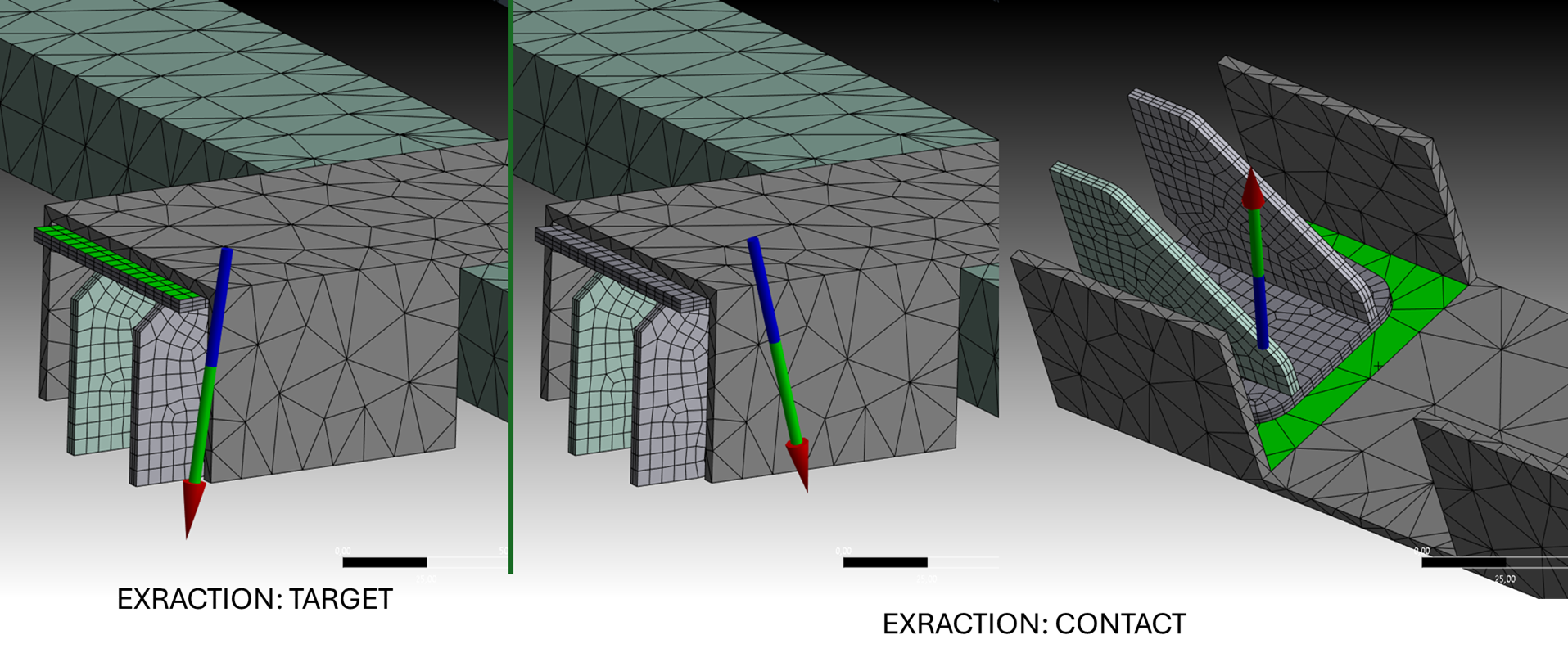
      I thought the contact forces should be opposite, I mean, at least in this case where two planar faces are in contact and both are not extender in all the solid.

      Initially I used "Augmented Lagrange", then changed to "program controlled" (which uses MPC I think).


    • John Doyle
      Ansys Employee

      Try forcing behavior to be Asymmetric, with contact scoped on smaller surfaces. Post process reactions on the contact side only.  There might be some nodal forces bleeding over on target side that have redundent scoping with other entities.

    • lvelasquez
      Subscriber

      Hi John,

      I solved the problem. I tried forcing Asymmetric and that didn`t help. The contact surfaces are already as small as they can be. I changed the detection method to projection, didn´t help. The only thing that worked was reducing the element size in the contact area, from 15mm to 5 to 2.5 mm. With this I got complete opposite force reaction. I did not changed the overall stresses, but now I feel more comfortable with the results.

      The thing is, all the elements are solid; I tried using surfaces to get shell elements but the "mid surface" tool in SpaceClaim, would generate a "Face thickness" in some parts with a non-editable zero value, which trigger an error when solving. Could this be the reason of this weird behaviour? Not having enough elements through the thickness that ansys "bled" some elements to the target side? I used the patch conforming method.

      Thanks.

Viewing 2 reply threads
  • You must be logged in to reply to this topic.