-
-
May 31, 2025 at 1:09 pm
01159423
Subscriber
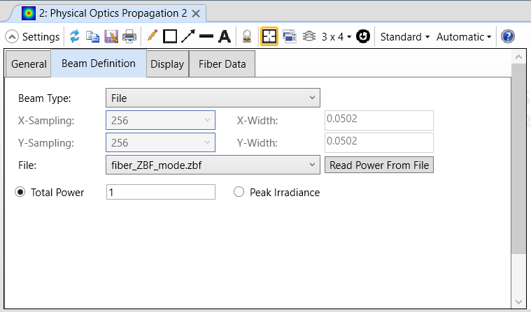
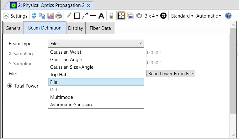
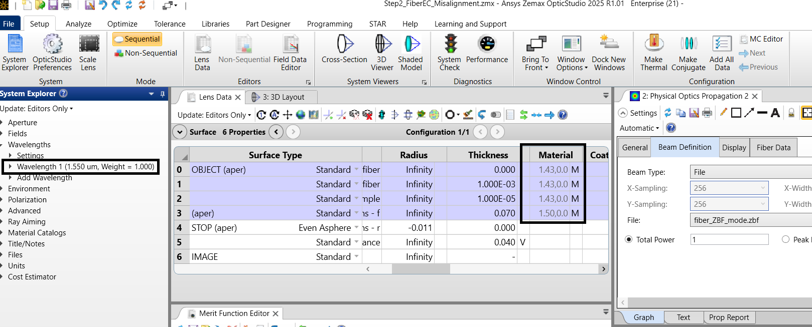
Hello everyone, I have a question related to simulations In FDTD and Zemax. Firstly, I did simulations of propagation fiber mode through 1 mm length and 200 um thickness lens. And according to examples I exported fiber mode from FDE solver as a source in zemax and used POP and it worked pretty well.
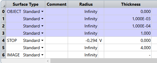
For example I got parameters of lens for 4mm focus, but then i wanted to do simulations in only FDTD to get nice picture of EM wave. Of course only in 2D because the size of simulation in 3D would be too demanding for my computer. And unfortunately i got different results.
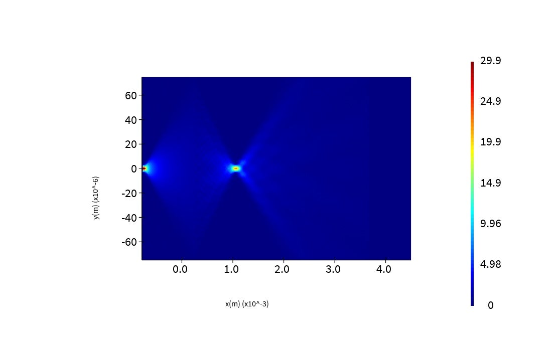
End of the lens is at 0 on x axis. As you can see simulated focus is closer to 1mm than 4 mm. As a BC i used stretched coordinate PML to avoid any reflections. I did mesh override close to the core of fiber and used mesh size is 0.1 in x and 0.4 in y directions. Do you have any idea why the results are different, or is it because FDTD is more accurate here? I already tried most of the things suggested in knowledge base, but nothing changed the results in FDTD.
-
June 2, 2025 at 7:28 am
Niki Papachristou
Forum ModeratorHi Subscriber,
Thank you for reaching out to us! May I ask you about which example you are refferering to and what you mean by propagation fiber mode through 1 mm length and 200 um thickness lens. There are several parameters that you need to make sure that they are the same for both simulations. My first thought while reading your post went on the source. Are you using the same source on the FDTD simulation (extracted from FDE) with the one on Zemax?
Unfortunately, it is hard for me to fully understand you simulation without your files. May I ask you if you are eligible for support? If yes, is it possible to open a case through our portal so you can attach your files. This way I will be able to pick up your case, investigate your files and resolve your question quicker. If not, I am still happy to help you through this forum.
Kind Regards,
Niki
-
June 5, 2025 at 8:35 pm
01159423
SubscriberUnfortunately i think im not but still i will tell you more about simulation. If we are talking about source, in lumerical, fiber modes are calculated by the structure and parameters of fiber and directly after end of the fiber there is a lens which is 1mm long and 200 um wide, with wide of fiber to be125 um. And im optimizing focus of the lens by changing the curvature of the last surface of the lens. So according to included image from FDTD there is 1mm long lens from the start of simulation its end is slightly after 0 on x axis and after that focusing of propagating beam is happening. And in zemax is the same but there is faster optimization process due to merit function. And the example which i mentioned is "Fiber-to-Chip Edge Coupler with a Microlens". This is almost the same case which i have done in zemax, but it FDTD i have different results. Can you guide me which parameters would be a problem here?
-
-
June 6, 2025 at 8:05 am
Niki Papachristou
Forum ModeratorHi Subscriber,
Thank you for coming back to me. If I am understanding your case correctly I think that in your case I would check the following to begin with:
- the source parameters to be the same in both Zemax and FDTD: On the example that we have online for example the source in POP is coming from the FDE simulation:

In your simulation are you using the same source or are you using other type of sources:
On any case, I believe the parameters of the beam definition have to be the same. - The material properties and the wavelenghts, again they have to be the same for both simulations:
- The geometry again has to be the same.
I hope that was helpful but feel free to come back to me.
Kind Regards,
Niki
- the source parameters to be the same in both Zemax and FDTD: On the example that we have online for example the source in POP is coming from the FDE simulation:
-
- You must be logged in to reply to this topic.
-
6420
-
1906
-
1457
-
1308
-
1022
© 2026 Copyright ANSYS, Inc. All rights reserved.

