Hi
First I would suggest going through our courses (e.g. , :
https://innovationspace.ansys.com/product/get-started-with-ansys-mechanical/
also go through the course on apdl scripting since combin39 needs apdl commands as shown in the video above.
As you are a research student you should have access to the ANSYS AI Assistant that appears on our website.
For instance if we ask for rigid and deform attachment we get this (it is very good):
--
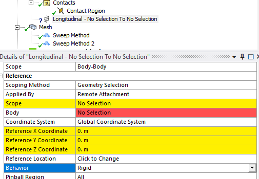
The difference between Rigid and Deformable remote attachments in Ansys lies in how the geometry is allowed to behave during simulation:
1. **Rigid Remote Attachment**: This setting does not allow the scoped geometry to deform. It is the only available option for Explicit Dynamics analyses. The Rigid setting ensures that the geometry maintains its initial shape, which can be useful when the object significantly stiffens the model at the attachment point.
2. **Deformable Remote Attachment**: This setting allows the scoped geometry to deform. It is a general-purpose option used when applying boundary conditions such as a force or mass through entities not explicitly represented as geometry inside Mechanical. This allows for more realistic simulation of how the geometry would behave under various loads.
I hope this helps clarify the differences! If you have any more questions, feel free to ask (ANSYS AI Assistant).
----
Finally look in the Ansys help manual where it should be explained how remote and direct attachment works (normally scoped to faces like shown in the first video ).
All the best of luck with your studies.
Erik
 This topic has been answered!!