We have an exciting announcement about badges coming in May 2025. Until then, we will temporarily stop issuing new badges for course completions and certifications. However, all completions will be recorded and fulfilled after May 2025.
Fluids

Fluids

Topics related to Fluent, CFX, Turbogrid and more.

Question About Different Result

    • werv2486
      Subscriber

      I’m currently working on a CFD simulation of a propeller using ANSYS Fluent, and I’ve encountered a puzzling result regarding boundary condition settings. I would really appreciate your insights or explanations.

      In my simulation, I’ve tried two different setups for the axial boundaries (top and bottom) of the fluid domain:
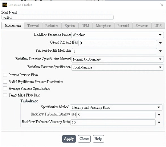
       1. Both top and bottom boundaries set as Pressure Outlet
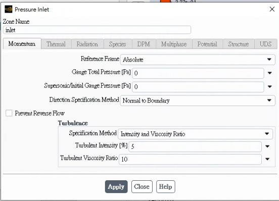
       2. Top set as Pressure Inlet, bottom set as Pressure Outlet

      The rest of the setup (geometry, mesh, rotating domain, solver settings) remains exactly the same between the two cases.

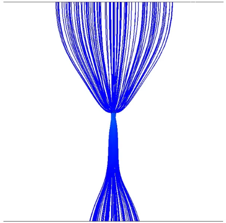
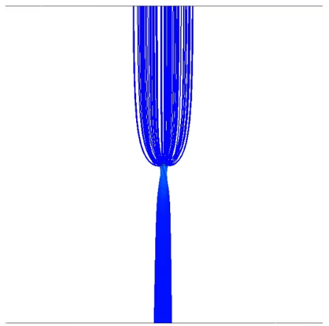
      However, the results differ significantly in terms of velocity streamlines and overall flow behavior. I’ve attached two streamline plots for comparison:
       • Figure 1: Results with both boundaries set to Pressure Outlet
       • Figure 2: Results with top boundary as Pressure Inlet and bottom as Pressure Outlet
      Could someone explain why this is happening? Is it due to how Fluent handles backflow or reference pressure at the outlet? Or is there a best practice when simulating open-boundary flows for rotating machinery like propellers?

      Thanks in advance for your help!

    • Essence
      Ansys Employee

      Hello,

      What pressure values you are applying while simulating both the cases? And how does the mesh look?


    • werv2486
      Subscriber

      Thank you for your reply!

      In both cases, I set the pressure value at the boundary to 0 Pa.
      Furthermore, the same model and mesh were used for both simulations—no changes were made to the geometry, mesh density, turbulence model, or solver settings.The following pictures show the boundary conditions on my inlet and outlet sides and the mesh structure used in the simulation.

      If there's anything else you need me to double-check, please let me know. Thanks again for your help!

    • Essence
      Ansys Employee

      Thanks for sharing the images. If you observe, the pressure in the Pressure-inlet is Total guage pressure and one in Pressure-outlet is Guage pressure.

    • werv2486
      Subscriber

      Thanks for your reply!

      How can I solve this problem?
      In the boundary condition setup interface, I can't specify whether the pressure is gauge or total pressure - there doesn't seem to be an option to change it.

      Could this be part of the reason for the difference in results?
      Any guidance on how to properly handle or check this would be greatly appreciated.

Viewing 4 reply threads
  • You must be logged in to reply to this topic.