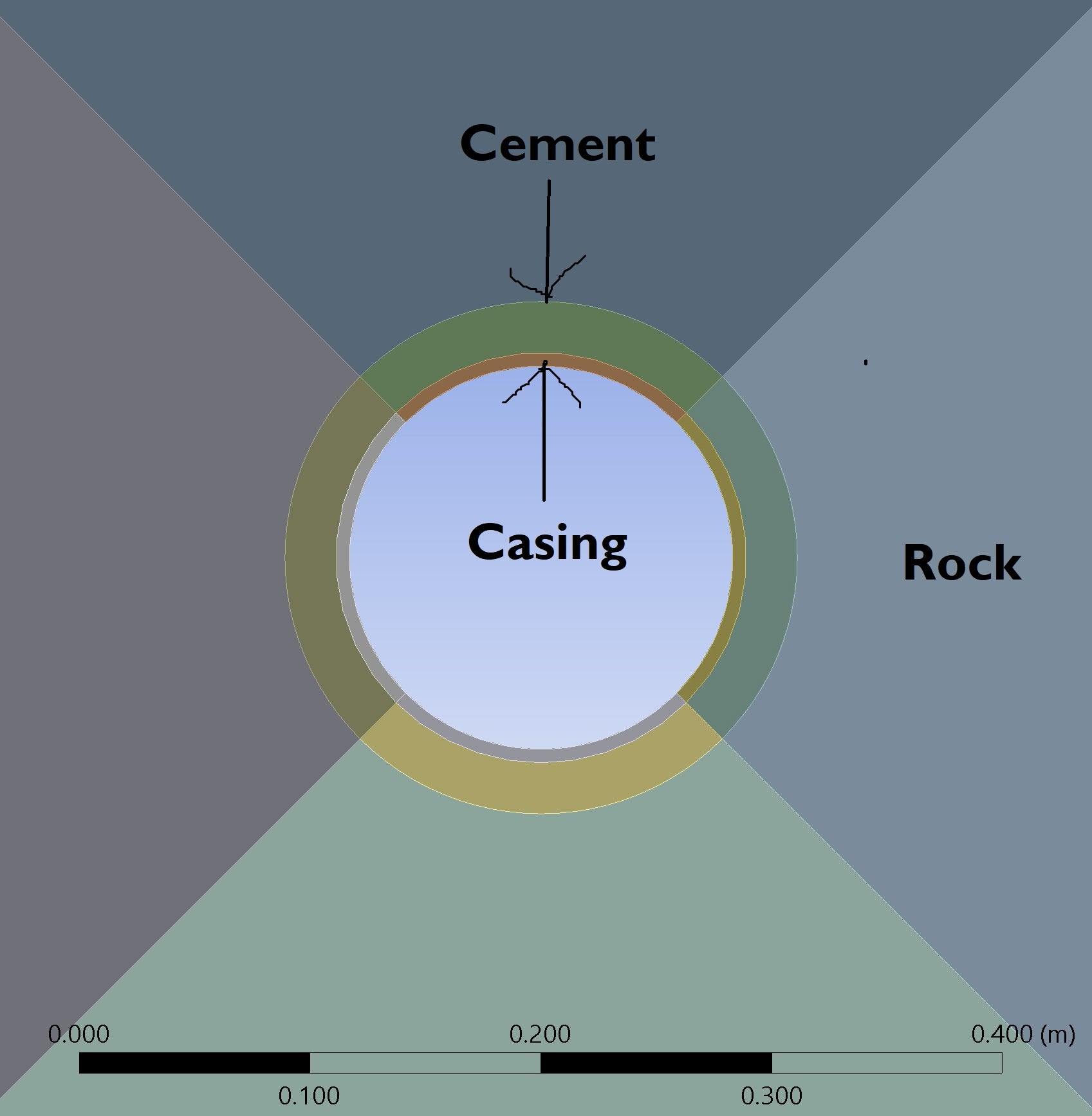
My 3D static structural model consists of three bodies (as shown in the attached figure): the innermost body is the casing, the outermost is the rock, and the cement is positioned between them.
When I attempted to create a semi-elliptical fracture on either the inner or outer face of the cement—located at the casing–cement or cement–rock interface, respectively—the meshing process failed. To address this, I changed the shared topology option in Design Modeler from “Automatic” to “None,” which allowed me to generate the mesh. I also set the batch connection to “Yes” to create a conformal mesh.
However, the solution terminated with the following errors:
*** ERROR *** CP = 62.594 TIME= 02:45:05
The command (CINT,SURF) supports only the 10-node tetrahedral element type
(SOLID187) when UMM is on. Please turn UMM off (CINT,UMM,OFF) or
remove the command (CINT,SURF) for crack set 1.
*** ERROR *** CP = 62.594 TIME= 02:45:05
The command (CINT,SURF) supports only the 10-node tetrahedral element type
(SOLID187) when UMM is on. Please turn UMM off (CINT,UMM,OFF) or
remove the command (CINT,SURF) for crack set 2.
As suggested, I used the following APDL command in the fracture definition:
CINT,UMM,OFF
However, after doing this, the solver gets stuck at 16% with the status "writing results," and it doesn’t progress even after a couple of hours. For reference, my mesh contains 32k elements. Previously, without the fracture, I was able to run a model with over 100k elements, which completed in 10–15 minutes.
I would greatly appreciate any suggestions or guidance on how to resolve this issue.