We have an exciting announcement about badges coming in May 2025. Until then, we will temporarily stop issuing new badges for course completions and certifications. However, all completions will be recorded and fulfilled after May 2025.
General Mechanical

General Mechanical

Topics related to Mechanical Enterprise, Motion, Additive Print and more.

Contact Question: Gluing deformed parts

    • andrew.mcneil
      Subscriber

      I have been using ansys Workbench mechanical for a few years, and have used different contacts.  

      I have a new problem instead of bonding two shapes with flat interface, one of the parts is deformed ("curved") so that to push these together the curved part has to elastically deform; imagine gluing a curved strip of wood to a flat surface, clamping the strip flat until glue cures, then remove the clamping.   I need to find the stress and final displacement of the the bonded assembly.

      I've tried a load-step to clamp 2 piecs into contact (using "bonded contact) then next load step releasing clamping load.  The problem is that the surfaces don't bond when forced insto contact.   The bent part initially has bonded contact a few points these do work - I've tested them - but when entire surface forced together no additional contact is formed.   I'm looking for some way to form bonded contact not from initial intimate contact but from contact under load.

      Any idea how to do this?    I think I can't so this with APDL commands (CEINTF etc) but I'd prefer using Ansys contact tools.

    • Shashidhar Reddy
      Ansys Employee

      Hi, Greetings! Thanks for reaching out. 

      Can you please let me know if my understanding is correct?

      Load step_1 : Curved part is bonded to flat part may be at the centre of curved part. Are these parts solids or shells? 

                             I am expecting the remaining surface of curved part is having frictional contact with the flat surface. (may be you have also created a similar bonded connection but it is in deactivated state)

                             Now, you are applying load on the curved part to bend it until it becomes flat. 


      Load step_2 : Keeping the clamping load for curing. May be you are changing the frictional contact to bonded contact using contact step control (activating a bonded contact which was in deactivated state in load step_2.

      Load step_3: You are now releasing the clamped load.

      Please correct me if I am wrong. Explaining the setup clearly with the snaps would be more useful for me to understand the setup perfectly.

      How to change contact type between load steps during an analysis? For instance, one want to have a bonded contact during the 1st load step and change it to frictionless in the 2nd load step. | Ansys Knowledge

    • andrew.mcneil
      Subscriber

      I am using solids

      I think your suggestion of changing contact type would work, I did not know that could be be done.   Let me try this with a simple model.

      Thank you very much

    • peteroznewman
      Subscriber

      I was interested to try this myself and built a 2D Plane Strain model to experiment with a CurvedPart and FlatPart. There is a Fixed Support at the left edge of the parts.

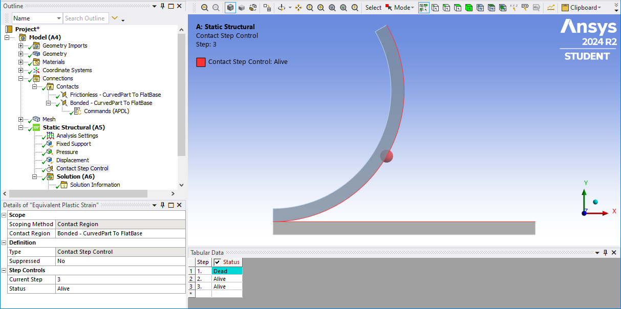
      I have a 3 step analysis and two contacts defined, Frictionless and Bonded. Contact Step Control sets the Bonded Contact to be Dead in step 1.

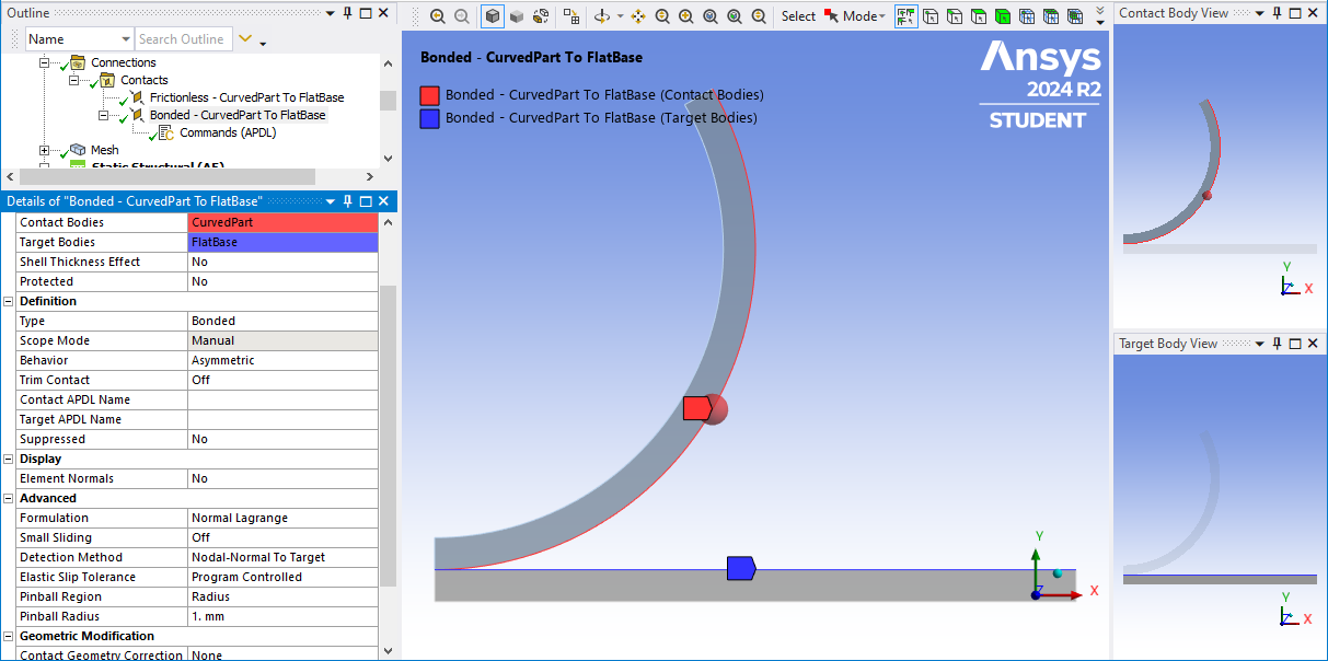
      The Frictionless contact has a large pinball radius of 30 mm which engulfs the entire two surfaces. The Bonded Contact has a small Pinball Radius of 1 mm and the Command Object under it is one line: KEYOPT,CID,12,3

      The Pressure load ramps on in Step 1, is maintained in Step 2 and ramps to zero in Step 3.

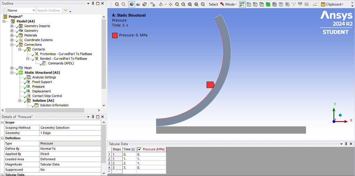
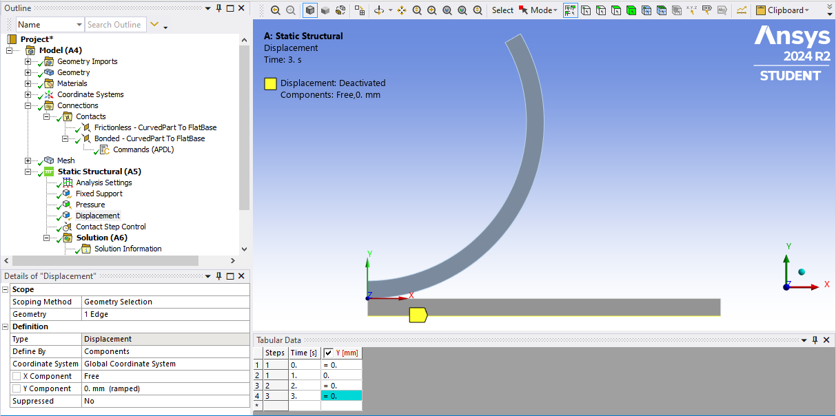
      The Displacement BC applied Y=0 to represent the surface supporting the FlatBase while the pressure is applied but that BC is Deactivated in Step 3.

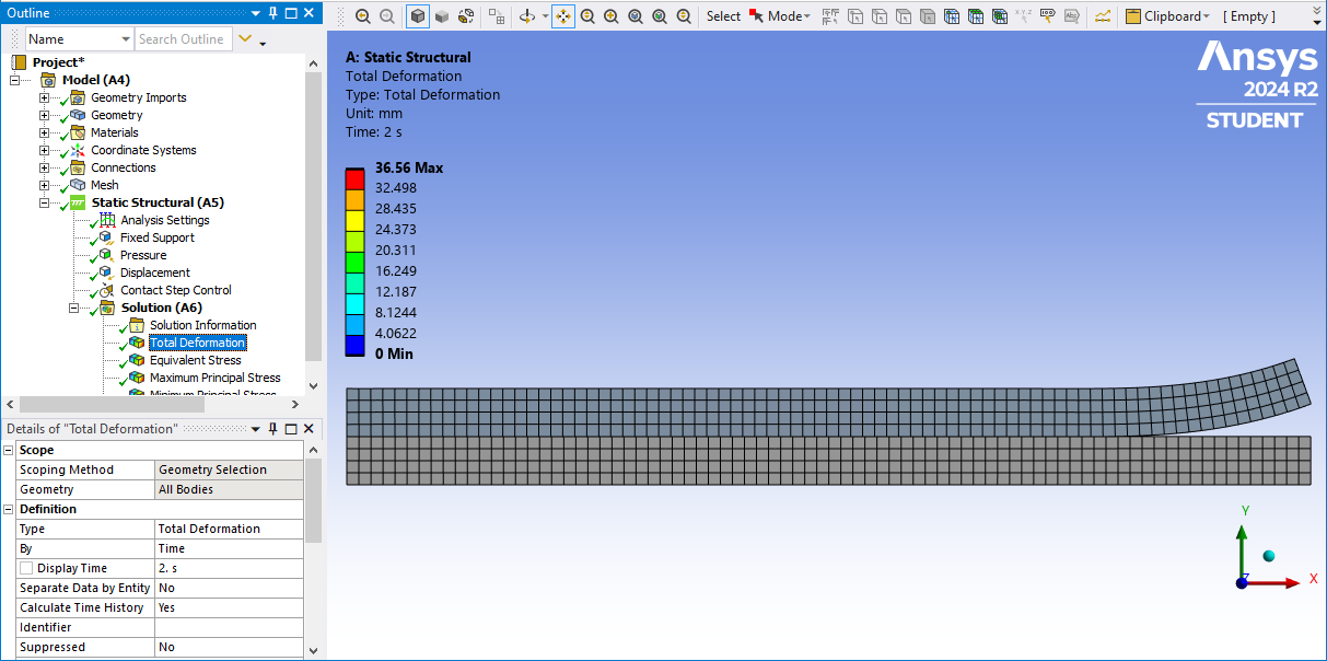
      The Analysis Settings have Large Deflection On and Auto Time Stepping On with Initial 100, Minimum 10 and Maximum 1000 Substeps. Here is the deformation at the end of Step 1 and 2.  I didn’t make the pressure large enough to push the last bit down.

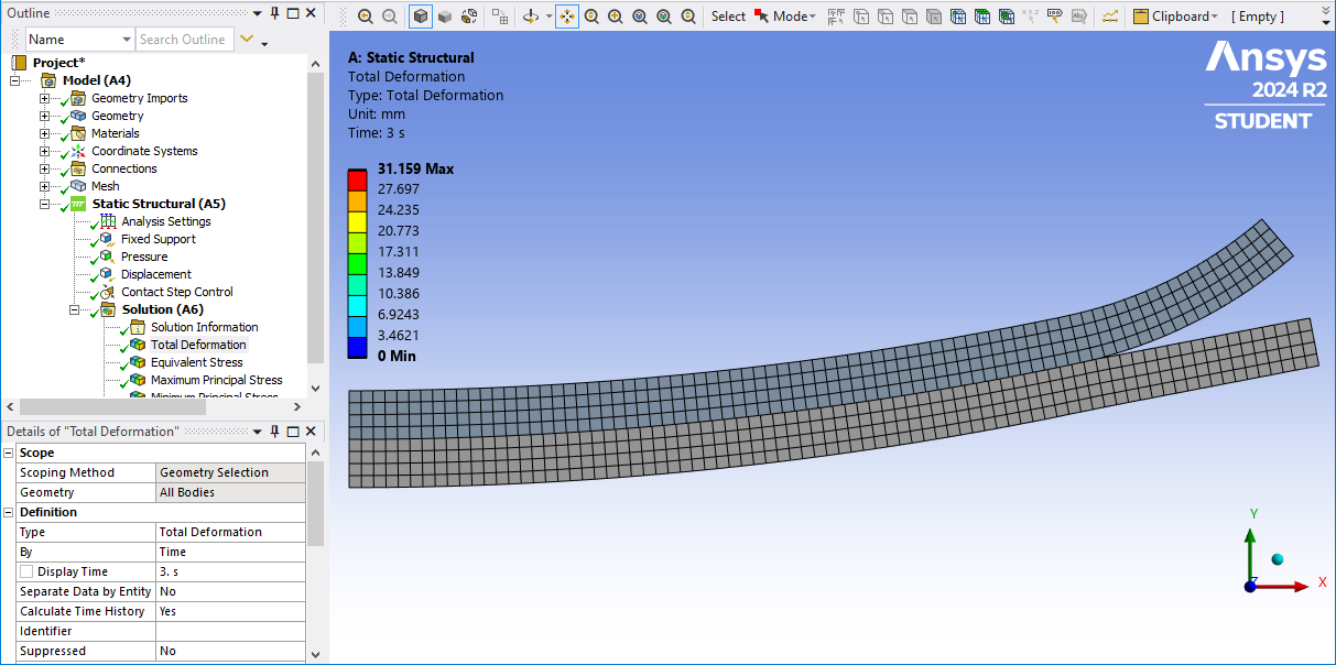
      Here is the deformation at the end of Step 3 when the displacement and pressure is deactiviated.

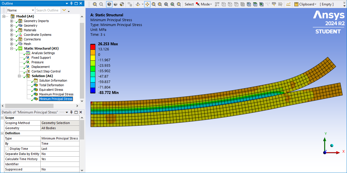
      Here are the tensile stresses in the bonded assembly.

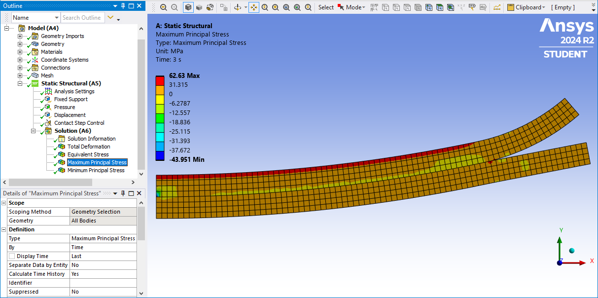
      Here are the compressive stresses in the bonded assembly.

Viewing 3 reply threads
  • You must be logged in to reply to this topic.