Ansys Assistant will be unavailable on the Learning Forum starting January 30. An upgraded version is coming soon. We apologize for any inconvenience and appreciate your patience. Stay tuned for updates.
3D Design

3D Design

Topics related to Ansys Discovery and Ansys SpaceClaim.

ExportPoint in DesignModeler

    • PippoLomi
      Subscriber

      Hi everyone,


      I use DesignModeler for create the FlowPath and blade Surface for a CFD analysis into CFX.


      Turbogrid works well with the files from DesignModeler.


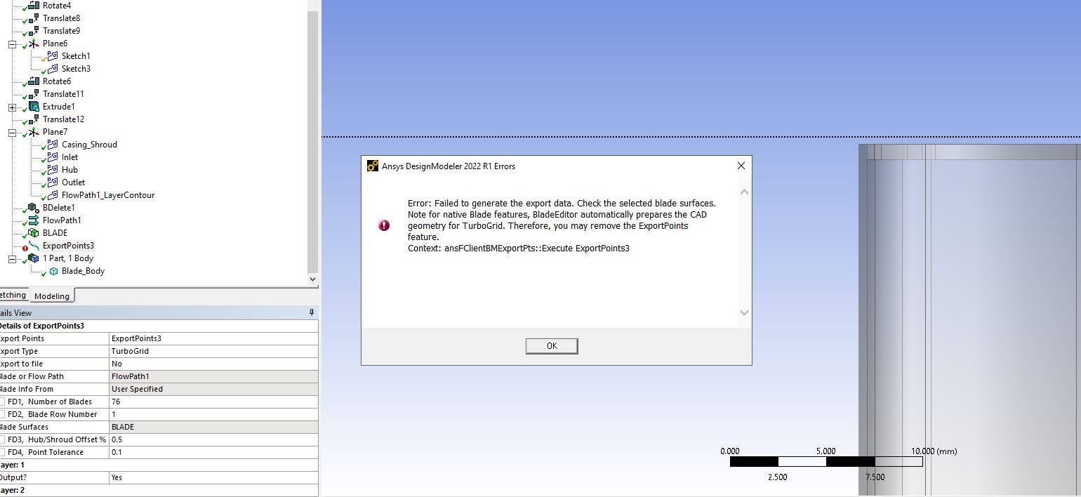
      But at the beginning, when I try to use "ExportPoint" feature in Blade Editor, it gave me an error


      Error: Operation would result in non-manifold bodies
      Context: Geometry Engine, while generating Feature ExportPoints1


      Then, I increase Hub/Shroud Offset to 1,3% and Point Tolerance to 0,5 (both present in "Detais of ExportPoint" window) and works fine.


      The error was related to the default values of the two variables written above (Hub/Shroud Offset and Point Tolerance).


      What is the meaning of the two variables?


      How can I model the geometric domain in order to decrease the tolerance ?


      Thank you

    • Rob
      Forum Moderator

      Non-manifold means something has come into contact with something and created a contact area of zero. Probably the blade tip was touching the shroud with a point or edge. Increasing the offset should (I think) give you more clearance; not sure about point tolerance. What does the documentation say?

    • PippoLomi
      Subscriber

      Good morning sir,


      the blade tip is in contact with the shroud, defined as a revolve surface. In fact, the shroud surface is generated using one of the two tip sides. The same for the hub surface. These two surfaces are used for draw a projected sketch on a specific plane, in which, also the inlet and outlet section are drawn, for define correctly the FlowPath BladeEditor  feature.


      So, what is your suggestion? Increasing the Hub/Shroud tolerance will not affect the blade shape like the blade height?  


      This last question is related to the graphic result of hub/shroud tolerance: when it is increased the green lines (that represent hub and tip profiles) move toward the midspan profile. Can this movement affect, in example, the blade height?


      Thank you

    • Rob
      Forum Moderator

      The blade can't contact the shroud in reality otherwise there tends to be a very loud and expensive noise. If you create the system with a small offset and review the model in DesignModeler is the blade the height you expect? 

    • PippoLomi
      Subscriber

      Good morning sir,


      I can create the hub/shroud surfces with an offset respect to the two imported 3D curve, but the clearance tip/shroud is added after this step, during meshing procedure in turbogrid.


      I use the two revolved surfaces only for create the hub and shroud contour, needed for "FlowPath" definition.


      Also, watching some videos, this seems to be the best method for define the contours needed in BladeEditor.


      Following your suggestion, how can I draw the shroud line, starting from the 3D line of the tip imported from the .txt file?


      Thank you

    • Rob
      Forum Moderator

      If you're in DesignModeler I'd use extrude/sweep/revolve: have a look at the tutorials for guidance. 

    • k1525166
      Subscriber

      I'm facing issues similarly, To give a tip gap, in the sketch projection I have increase the hight of the tip to get tip gap, however in the Export Points section, Im getting an error, see Below:

    • abhishekkumar.shingala
      Subscriber

      Every user who is performing this tasks for the first time would take original shroud position, I did same but it did not work then I use the blade tip without clearance and then export point features works.

Viewing 7 reply threads
  • The topic ‘ExportPoint in DesignModeler’ is closed to new replies.
[bingo_chatbox]