TAGGED: shell
-
-
March 27, 2025 at 10:11 am
tanmay.singhal
Subscriber
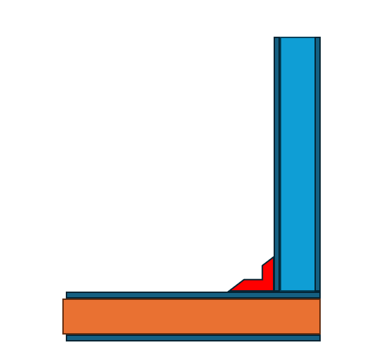
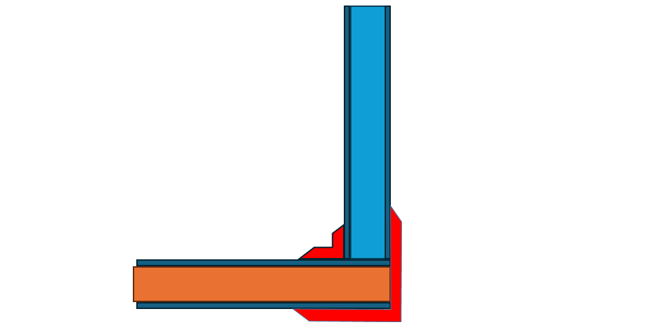
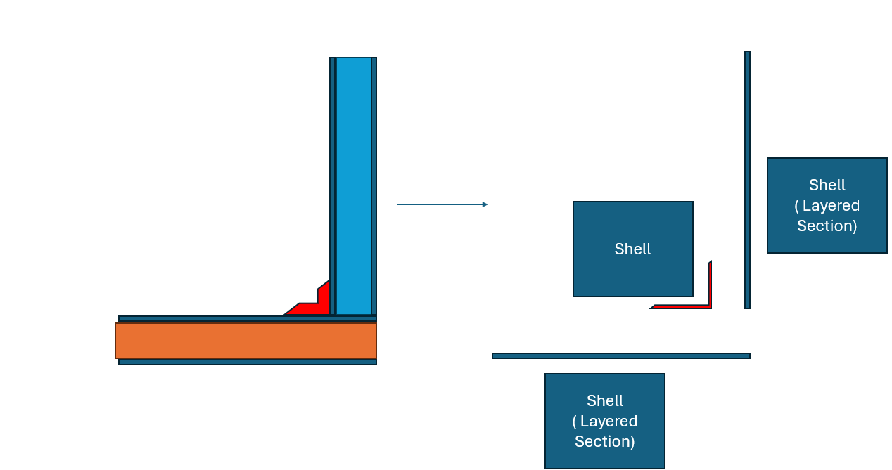
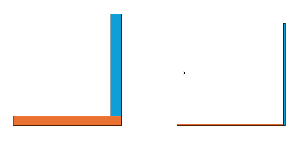
I have to reduce orange and blue plate to shell elements.
Â
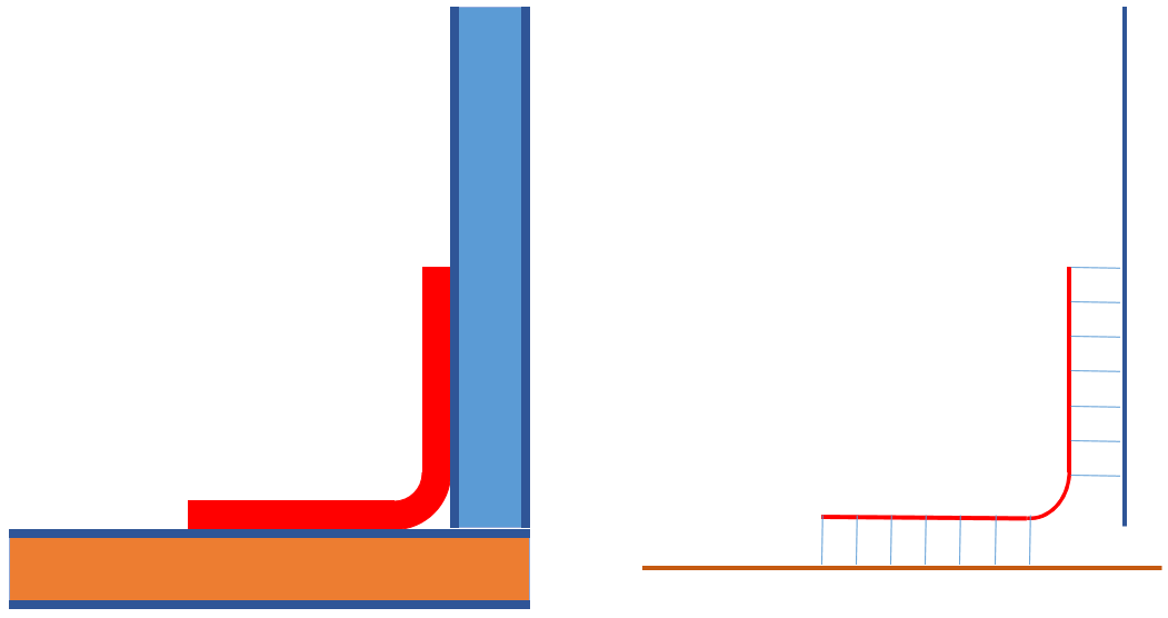
I have query regarding boundary condition. If i reduce it this way and attach edges( bonded contact for edges), so the outer face of blue ( right face) will be attaching with bottom face of the orange.
But in actual physical condition, Top of orange is attached with the blue.
Â
Do i have to activate some options?
-
March 28, 2025 at 1:43 am
Dennis Chen
Subscriberwhen you midsurface, turn off the thing that forces edges to extend.  in spaceclaim, just scroll down that window and it's checked by default.  I have no idea why this is checked by default, it should always be unchecked unless you have really good reason to check it.Â
-
March 28, 2025 at 10:26 am
tanmay.singhal
SubscriberThis extracted surface is not midsurface. Orange has bottom surface extracted and blue has top surface extracted.Â
The plan is to use layered section to simulate honeycomb sandwich simulation.
Â
Red component is the equal angle or L-angle for panel attachment.
I dont want red components in simulation. I only want to reduce both panels to shells and carry out the analysis.
-
March 29, 2025 at 2:34 pm
peteroznewman
SubscriberI would be wary of excluding the angle clip and simply bonding the two sandwich panels together because the panels are much stiffer in bending than the angle clip. The lower bending stiffness of the angle clip creates a hinge between the two panels. This would be important to represent for deformation or modal frequency.ÂIf the design had an angle clip on the inner facesheets and a larger angle clip on the outer facesheets, that connection would be much closer to the panel stiffness. With that design, you could ignore both clips. -
March 30, 2025 at 11:47 am
-
March 30, 2025 at 2:27 pm
peteroznewman
SubscriberDo the angle clips have a blend radius? This is common for sheet metal or CF layups. In that case, you should add the blend radius to the clip geometry. Imprint the flat faces of the angle clip onto the HC sandwich panel and use Bonded Contact between the panel faces and the angle clip faces. That will leave the blend radius free to create the lower stiffness hinge I described above. The image below illustrates midsurface extraction of the panels and the clips.
If you extract the inner faces of the panel and the outer faces of the angle clip and make the Offset Type to Top or Bottom as needed, then the bonded contact will use zero-length connection elements. You could even eliminate bonded contact if you use Shared Topology and use a unique layered section for the areas that have the flat clip faces above the inner facesheet, while the blend radius is a plane shell section.
-
- You must be logged in to reply to this topic.
-
6485
-
1906
-
1458
-
1308
-
1022
© 2026 Copyright ANSYS, Inc. All rights reserved.


