TAGGED: displacement, fea, udf
-
-
March 23, 2025 at 2:01 pm
Farah
SubscriberHi,
I have a plane that is positioned inside a cylindrical structure. I want to apply a specific displacement to every point on that plane and observe how the cylinder deforms as a result. I think not sure that i should do this analysis in the Static Structural module of ANSYSI think I might need to write a User-Defined Function (UDF) to assign the displacement values (not force/pressure) point-by-point on the plane. However, I'm not sure whether Finite Element Analysis (FEA) platforms support this kind of custom per-point displacement input?? Where can i do that?
If anyone has any ideas or experience with doing this or any idea, I’d really appreciate thehelp. Thanks!
-
March 23, 2025 at 3:44 pm
peteroznewman
Subscriber
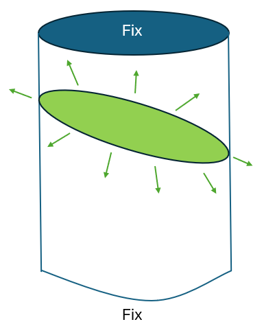
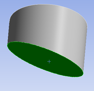
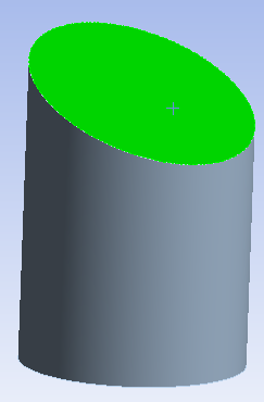
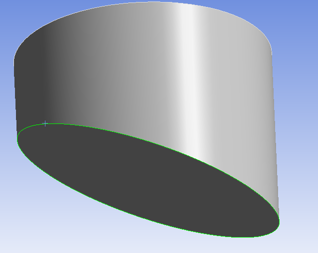
You can certainly apply a unique displacement to each node in a plane in a Static Structural analysis. Open the cylindrical solid in SpaceClaim and on the Design tab, create the plane you want and use Split Body. Then on the Workbench tab, use the Share button so there is a set of shared nodes on that plane.
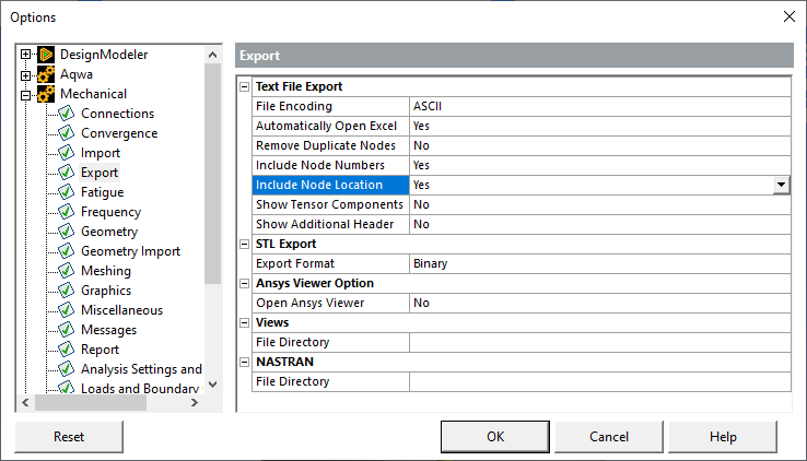
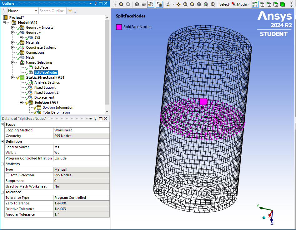
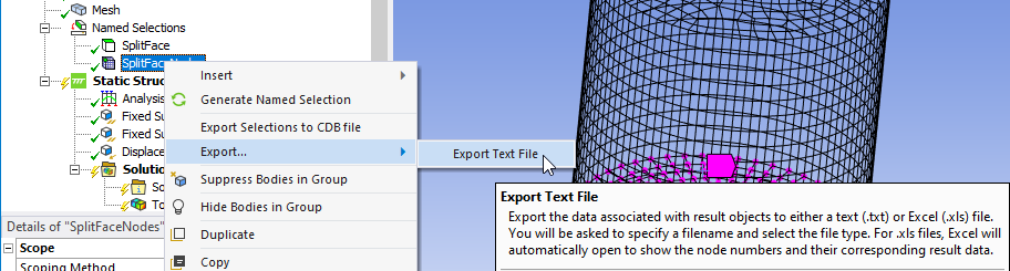
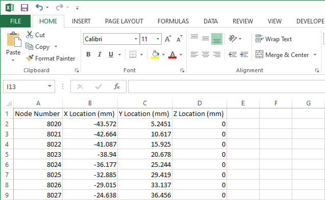
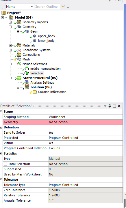
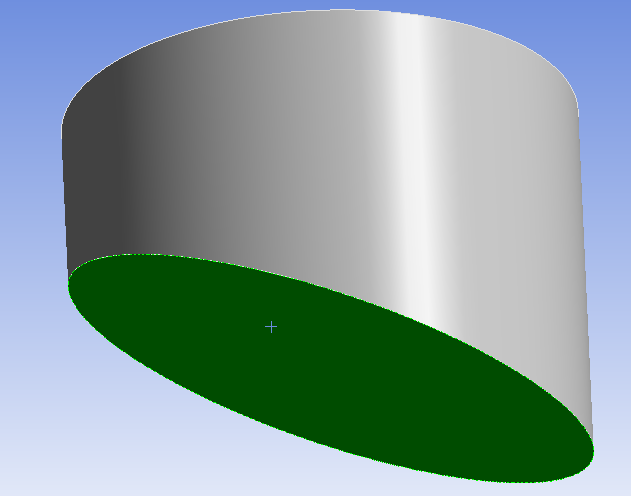
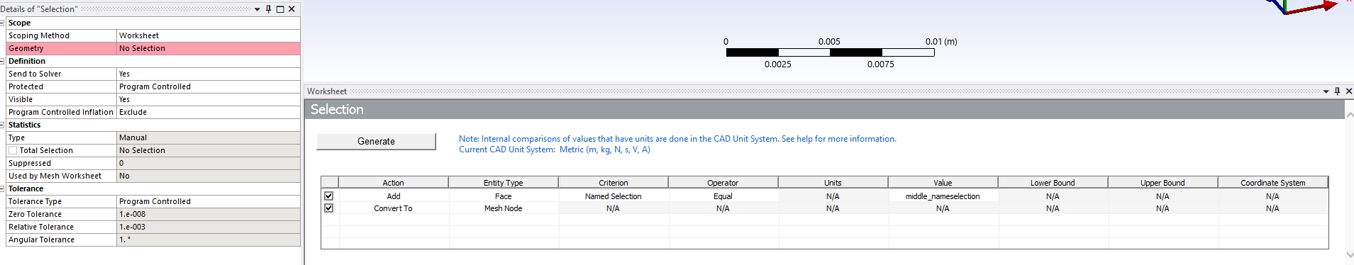
If all the nodes were to be moved by the same amount, that would be easy, but I think you want to move each node by a unique amount. In Mechanical, create a Named selection for the face that was created by the split plane. Convert that to a Nodal Named Selection. Export the list of nodes in that plane with their x, y, z coordinates. I assume you have some formula that gives the x, y, z displacement for each node given the x, y, z coordinates. In an Excel spreadsheet, import the node list and create 3 columns for the displacement in x, y and z.
Once you have that, you will need to reformat that data into APDL code that applies the displacement to each node. You will use the D command. For example, say you have node 42 that is to be displaced by (0.1, -0.2, 0.3). You will need 3 lines of code for each node and you will insert that code using a Commands object in the Static Structural model:
D,42,UX,0.1
D,42,UY,-0.2
D,42,UZ,0.3 -
March 24, 2025 at 3:10 pm
peteroznewman
Subscriber-
March 24, 2025 at 7:19 pm
Farah
SubscriberHi Peter,
Thanks a lot for your time and help, I reallyyy appreciate it.
I’ve been following your steps, but I ran into a couple of issues:
In the “Named Selection” step, after I split the geometry, I ended up with two parts, so now there are two planes. Can I define the named selection on either the top or bottom part; does it matter? I just want to make sure I’m doing it right.
After I create the named selection, I try to right-click and convert it to a Nodal Named Selection, but I get an error (screenshot below). I tried selecting all the edges and also tried the face, but neither one worked; I couldn’t move forward.
Because of this, I haven’t been able to try exporting the list of nodes, converting the data into APDL code, or using the
D
command.I hope you can help me figure this out. I can also share the cylinder model if needed; it’s very basic, just a circle that I pulled into a cylinder.
Thanks again,
Farah
-
-
March 24, 2025 at 7:49 pm
peteroznewman
SubscriberHi Farah,
Yes, there are two bodies, but if you did not skip the Share step in SpaceClaim, there is only one face that they both share. "Then on the Workbench tab, use the Share button so there is a set of shared nodes on that plane."
Cheers,
Peter-
March 24, 2025 at 7:56 pm
Farah
SubscriberHi Peter
Thanks for your swift reply
I had to generate mesh to see those nodals
Thanks a lot for your help!
-
-
- You must be logged in to reply to this topic.
-
2918
-
970
-
852
-
599
-
591
© 2025 Copyright ANSYS, Inc. All rights reserved.