Fluids

Fluids

Topics related to Fluent, CFX, Turbogrid and more.

ANSYS AQWA – Ratio of distance error

    • S.S.S.ShankaVasuki
      Subscriber

      Hi,

      I am trying to simulate a multiconnnected rigid body floating system with the following specifications:

      The simulation runs without any errors for irregular waves with low Hs but when I try to simulate a rough sea state with a JONSWAP spectrum with Hs- 2m, gamma - 3.3 and Tp - 7s, it results in this error:

      " Ratio of the distance change exceeded by 75%. The current distance (d_cur) between Panel#1728 on Structure#2 and Panel#2732 on Structure#3 within a hydrodynamic interaction group is 0.739. The distance (d_ini) of these panels in Aqwa-Line is 5.000. Stopped at Time = 535.00."

      I am not quite sure on why this occurs and how to fix it. Could someone please help me out with fixing this error. I have also attached the screenshot of the error below for better understanding. Thanks!

    • Shuangxing Du
      Ansys Employee

      Aqwa time domain analysis (Hydrodynamic Response)  uses the hydrodynamic database generated by the frequency analysis (Hydrodynamic Diffraction).  In the Hydrodynamic Diffraction, you may have selected the hydrodynamic interaction group consisting of all the 16 structures shown in the picture above.  For the hydrodynamic interaction structures, the hydrodynamic properties are affected by the relative distance between the diffraction panels of the adjacent structures. In the time domain analysis, when the relative distances betweem the diffraction panels are changed significantly, the error message will be issued.

      As the gaps between the structures in your model is relative narrow, the ratios of relative distances of the diffraction panels on the hull surfaces in the gaps are more sensitive to the motions of the structures. To avoid much problem, please set the surface type of the surfaces facing the gaps to be  non-diffracting (5.5.1. Surface Body). 

    • S.S.S.ShankaVasuki
      Subscriber

      Hi,

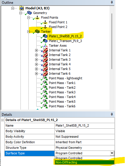
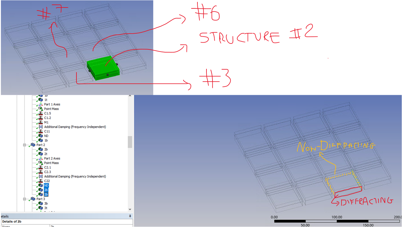
      I tried to set all the faces that face the gap as ‘non-diffracting’ and the other faces to be diffracting. The method in which I did this was design modeller > select only the faces that face the gap for each part > create surface from face > set that as non-diffracting in Geometry in AQWA.

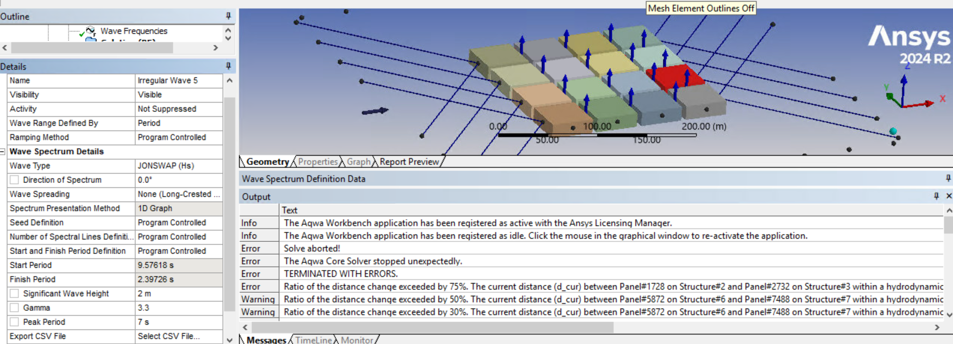
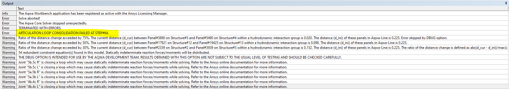
      However, when I do that, I get the following error:

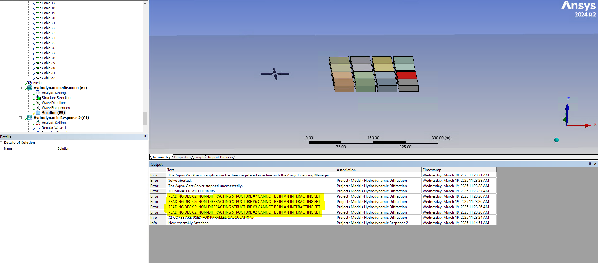
      To just take structure #2 as an example as shown in the errors, this is how I have set the faces as diffracting and non-diffracting.

      Could you please let me know on how to fix this?


      Thanks!


    • Shuangxing Du
      Ansys Employee

      It should be done in Aqwa Editor instead.

      As shown below, if a structure consists of several surfaces, the surfaces between the gap can be set as non-diffracting

    • S.S.S.ShankaVasuki
      Subscriber


      Yes, I understand now and the simulation runs without any errors.

      But I see a major difference in the actual responses (hydrodynamic response analysis) when all the surfaces are diffracting and when I set some surfaces to be non-diffracting

      To give an example of the difference, when I ran a simulation for 400s, the maximum pitch response when all surfaces are diffracting is 10deg and this drops to 1.5deg when I set some of the surfaces to non-diffracting.

      But then I am wondering whether this assumption is indeed correct as I am seeing a large difference in the actual responses from both these approaches.


    • Shuangxing Du
      Ansys Employee

      Yes, this is the problem when the relative motions between the hydrodynamic interaction structures. The hydrodynamic properties may change significantly with/without the diffraction panels on the hull surfaces in the gaps. We may accept these results for the larger motion cases.

    • S.S.S.ShankaVasuki
      Subscriber

      Yes, but is there a way to understand how such a system would behave when the waves are rough? Because when all the surfaces are diffracting I can run a simulation for 400s without any errors and then the error relative distance pops up.

      So I have two questions:
      1. What exactly do you mean by "We may accept these results for the larger motion cases."?

      2. Can I rely on the responses of a 400s second simulation?

      3. Is there any other way in which I could realize the response of such systems?

    • Shuangxing Du
      Ansys Employee

      (1) Setting the surfaces to be non-diffracting is a work-around approach, the results may not be accurate.

      (2-3) In your original model time domain input data file, you can insert the debugging option to ignore the error message and let the program run, see below

      Then you could compare the results by the original model and the new model in which some surfaces are set to be non-diffracting.

    • S.S.S.ShankaVasuki
      Subscriber

      Hi,

      i enabled the debug option via a python script and I get another error saying " ARTICULATION LOOP CONSOLIDATION FAILED AT STEP#64." as shown below

    • Shuangxing Du
      Ansys Employee

      OK, it means that your original model is not suitable to large wave condition due to the unrealistic hydrodynamic interactions (by this debugging option to convert the error message to the warning message).

Viewing 9 reply threads
  • You must be logged in to reply to this topic.