-
-
March 2, 2025 at 5:05 pm
leila
SubscriberHello,
I have two parts defined as shells, and I have applied a bonded contact between their surfaces. Since they are shells, there is an inherent gap due to their thickness. I have specified the upper and bottom sides for surfaces 1 and 2 in the contact definition.
However, ANSYS does not recognize this as a bonded joint. Even after using the auto-detect pinball region, it still fails to establish the bonded contact.
I would appreciate your help in resolving this issue. Your prompt response would be greatly appreciated.
-
March 2, 2025 at 5:36 pm
peteroznewman
SubscriberPlease show an image of the bonded contact faces with the red/blue colors that show when the contact is selected in the outline.
Try typing in a larger number for the pinball radius.
Try turning on shell thickness effect.The top/bottom sides may not be correct, you might need top/top, bottom/bottom or bottom/top depending on the normal of the surfaces you are selecting.
-
March 3, 2025 at 12:15 am
leila
SubscriberThank you for your consideration. Normal of the surfaces are in opposite directions as shown in the picture.
Thickness of the upper shell is 2mm downward and thickness of the lower shell is 1 mm downward and a bonded contact is defined between the top surface of the upper shell with the bottom surface of the lower shell. I could not turn on shell thickness effect as its cell turned to yellow.
As your recommendation, I tried to increase pinball radius to 2.5mm instead of 2mm which was automitaclly detected by Ansys (equal to the thickness of the upper shell). The contact status is changed from red (Far open) to orange (closed but has a large amount of gap or penetration).
However, there should be no penetration since I want to define contact debonding using CZM on this bonded contact joint. when I use this bonded contact definition for contact debonding (pinball radius=2.5mm), after a while, I see penetration in the model and simulation cannot capture debonding.
I greatly apreciate your guidance on how I can solve penetration issue. Thank you for your time in advance.
-
March 3, 2025 at 1:35 am
peteroznewman
SubscriberHello Leila,
Please review this discussion which has some relevant information on contact debonding and fracture models.
https://innovationspace.ansys.com/forum/forums/topic/does-interface-elements-or-contact-based-debonding-using-czm-exist-for-shell/The author of that discussion, Dennis Chen, made his own video on this: https://www.youtube.com/watch?v=f8wyk9iB1_c
Regards,
Peter
-
March 3, 2025 at 2:52 am
Dennis Chen
SubscriberHi Leila, I would recommend enable "shell thickness effect" in your bonded contact.  I was able to test this out in my dummy model and it works just like a contact based debonding between solid elements.  I believe the reason we want to use shell thickness effect is because Contact174 elements are auto-generated in the background (as shown below).  If we don't use thickness offset, this may affect how contact174 elements are generated.  This is also where I dislike Ansys Mechanical because it's doing too much for users to make it easy.  it works great when it works, when it doesn't, it makes it harder to figure out why.Â
If you want to use interface elements for CZM, it doesn't work for shell... As I mentioned in the video, interface elements Inter202, Inter203, Inter204 and Inter205 are the available interface elements and they are used to link 2D, 3D solids and 3D solid-shell elements respectively and therefore, currently there's nothing directly linking shell elements using interface elements (no such element# exists for shell based on the documentation). Â
I asked this question in one of the earlier post which is what Peter had posted above.Â
Hope this helps.Â
-
March 5, 2025 at 4:22 am
leila
SubscriberHello,
I greatly appreciate your consideration. What you have mentioned is somehow unclear to me. I don't want to model cohesive elements but instead I want to model its behavior as CZM (cohesive zone modelling) using contact debonding in Ansys. The geometry is as simple as a single lap joint with a tensile displacemnet at the end. Do you mean that Ansys cannot cover CZM considering shell elements?
As your recommendation, I modelled parts as mid surfaces and turned on the shell thickness effect considering bonded joint. They have a geometric gap equal to their thickness.ÂAfter defining contact debonding and running the simulation, the solution does not converge ans stops at a point. I see CZM is not activated and I also see penetration between the two parts.
These are the element types being used and I don't know if I can change the type of elements used by ANSYS and if it can help anyway.
I greatly appreciate it if you could give me a hint at some point.
-
March 5, 2025 at 4:42 am
Dennis Chen
SubscriberHi Leila, I attached some images below, and I can verify CZM works for shell elements based on contact debonding.  in Ansys workbench, you don't generate any "cohesive elements" like you would do inside LS-Dyna or abaqus.  You either do contact debonding, or you use interface elements.  Contact debonding requires contact pairs and interface elements requires matching interfaces/nodes.  Contact debonding works for shell-shell pair while interface elements doesn't work for shell-shell pair.Â
one difference I seem to notice is your nodes not being aligned.  increase mesh density could alleviate this so it's worth a try.Â
-
March 9, 2025 at 1:37 am
leila
SubscriberHello Dennis,
I truly appreciate your explanation. I attempted to use CZM for contact debonding, but I encountered convergence errors. Reducing the mesh size only increased the simulation time, yet the error still occurred at a point. Interestingly, the contact pressure values before the solution diverges appear unrealistic. They should be around 10–15 MPa, but in my case, they are less than 1 MPa.
I have put considerable effort into making it work. The geometry is quite simple, yet I’m unsure why Ansys is unable to solve it. I have attached the archive file, and if you could take a look, I would be extremely grateful.
https://drive.google.com/file/d/1TSk3W-X5cf5OR7OtyIyEmabS3g4sFHdb/view?usp=sharing
-
March 9, 2025 at 2:01 am
Dennis Chen
SubscriberÂ
Hi Lella, your issue is with your CZM model… I was able to use my own CZM xml file in your model and it was able to solve to completion. Nothing else was changed except for the material model for CZM.  I can also confirm you did everything else correctly.Â
where did you get the CZM model for DP460? Upon closer inspection of your CZM model, the model 1 and mode 2 fracture energy looks very low which is why you are getting convergence issues.  DP460 is an epoxy adhesive so my guess is that something about this CZM model is off…
DP460 should be a 3M product and if that’s indeed the case, I would suggest you visit https://digitalmaterialshub.3m.com/support-center and submit a support case. Â
Thank you
Â
-
March 9, 2025 at 4:01 am
leila
SubscriberHello Dennis,
Thank you very much for your time. Could you please send a screenshot of the adhesive properties for fracture energy based debonding you used for CZM?
I obtained these adhesive data from an article I read, but unfortunately they appear to be incorrect, which has led to my confusion.
-
March 9, 2025 at 4:07 am
Dennis Chen
SubscriberHi Leila, my numbers are mostly dummy. however, multiply your GI and GII fracture energy by 10 and you get approximately what I had.  Fracture energy is the area under the curve of your traction separation function and it effectively defines how much load the bond can take before fully break apart (with damage intiation and evolution behavior built in the TSC).  If the energy is too low, you obviously would get convergence issues as that's equivalent of having a very large displacement for a very small amount of force in an implicit static structural problem.
Â
-
March 10, 2025 at 12:45 am
leila
SubscriberHello Dennis,
Thank you very much for your illustration. Your recommendation made the simulation work! However, the contact pressure values don't seem realistic. The reaction force reaches 7 kN, which seams to be reasonable, but the contact pressure values are below 1 MPa when they should be around 20–25 MPa. Do you have any idea what might be causing this issue?
-
March 10, 2025 at 1:24 am
Dennis Chen
SubscriberHi Leila, I would ask how you know your expectation of contact forces or contact pressure is correct.  If you simply multiplied GI and GII energy by 10 like I suggested, the resultant CZM is not a valid model.  The 1st step is to make sure you have a good CZM model from a reputable source (such as the manufacturer of the DP460 you try to model) and then you look at what the expectation should be based on the actual test data used to generate the CZM model. Â
Best Regards
-
March 12, 2025 at 2:22 am
leila
SubscriberHello Dennis,
Thank you for your response. It seems that the issue is not related to the adhesive properties but rather to the modeling approach.
To verify this, I created an equivalent 2D plane-stress model (similar to what you demonstrated in your video) and compared the results with a shell-based model. I tested both with the given adhesive properties and an alternative set. While the reaction force values are in a similar range, the contact pressure in the 2D model is significantly higher and appears more reasonable compared to the shell model.
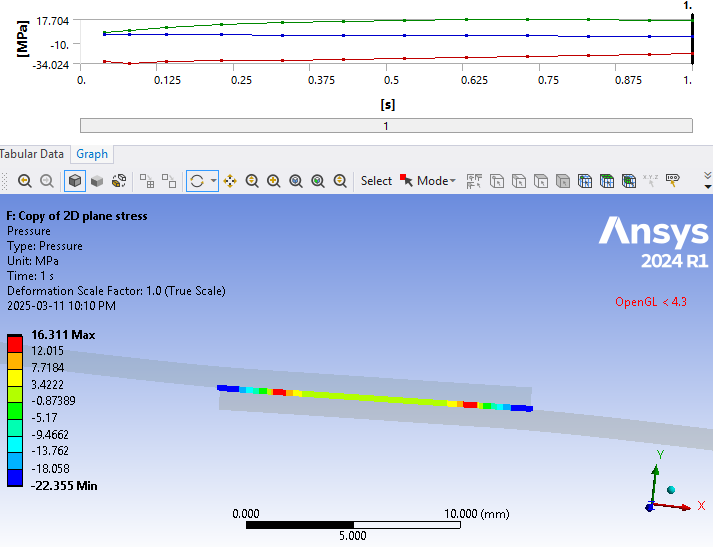
Here is the contact pressure distribution for the 2D plane-stress modeling:
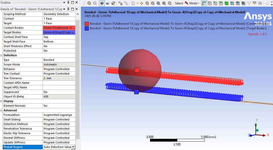
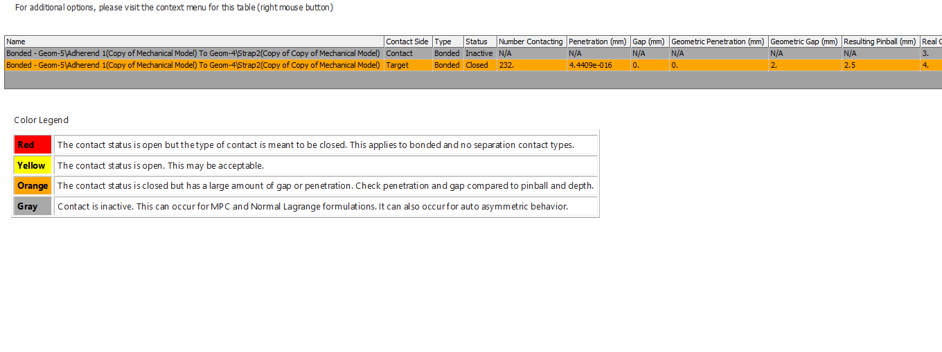
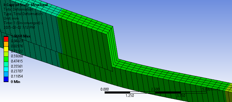
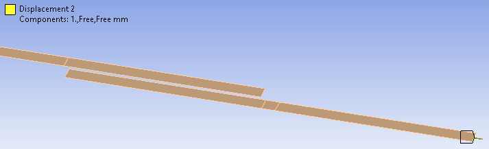
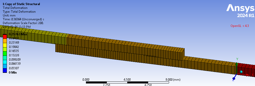
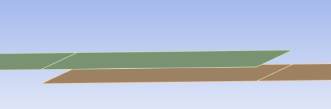
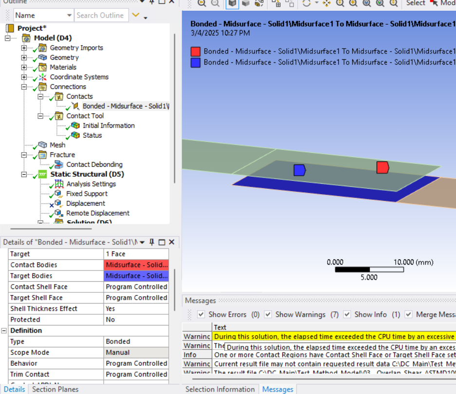
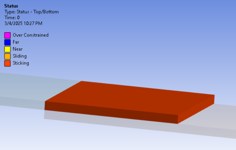
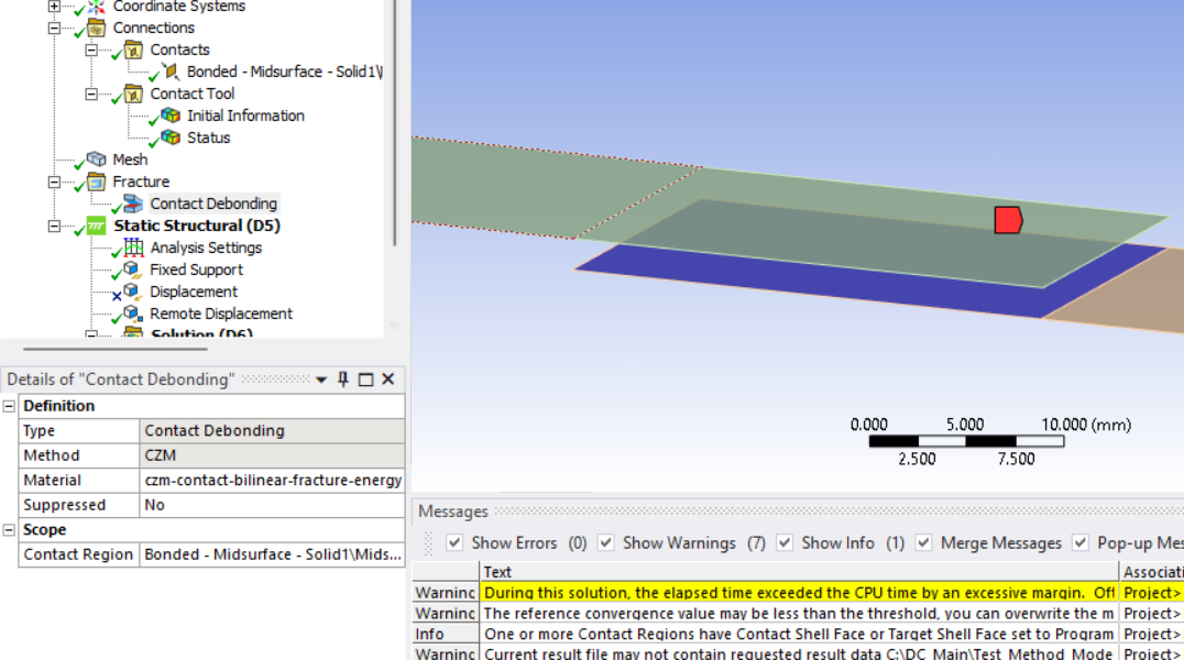
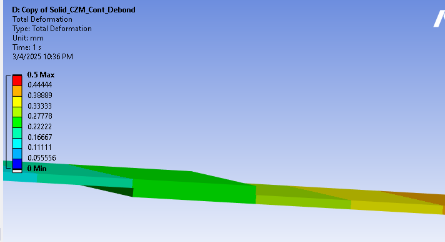
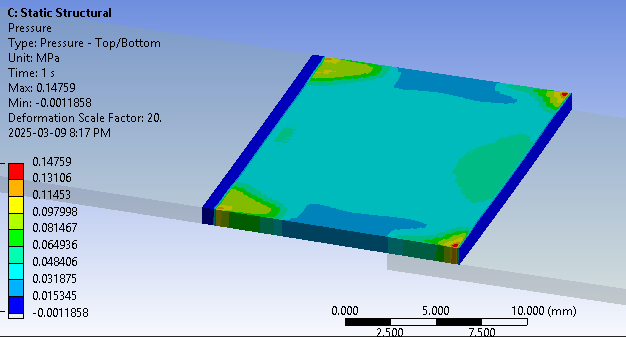
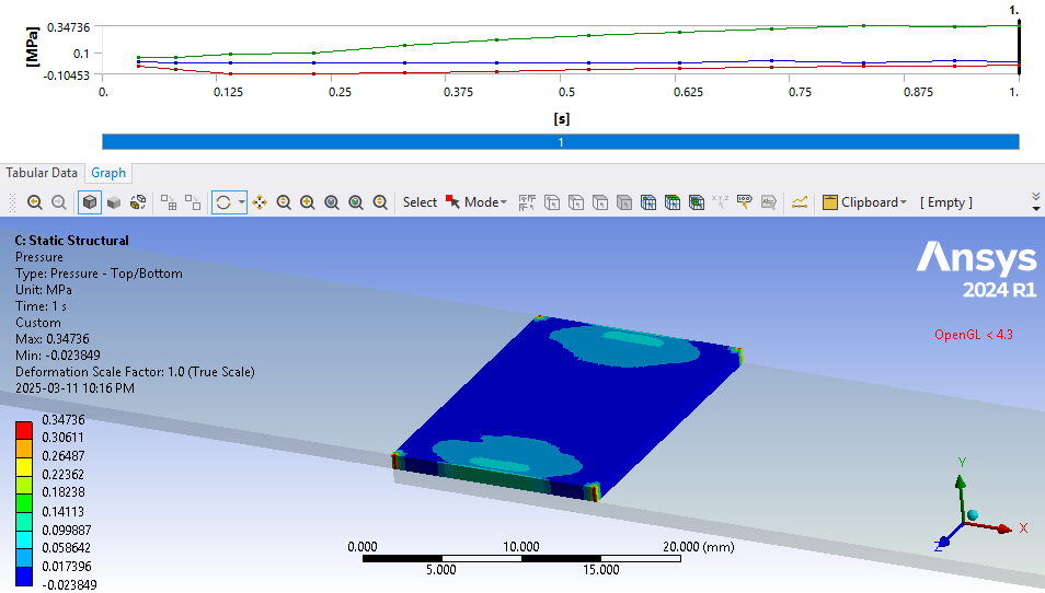
The contact pressure distribution for the shell modeling:
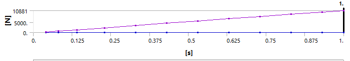
The reaction force for the 2D plane-stress modeling:
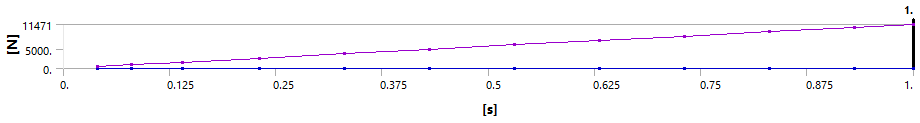
The reaction force for the shell modeling:
I would appreciate it if you could guide me on this matter.
best regards
-
March 12, 2025 at 1:06 pm
Dennis Chen
SubscriberÂ
Leila, I tested this on both 3D solid and 3D solidshell elements and they all have the same contact pressure, and look similar to the 2D version, but Shells do not.  At a glance, it seems like the substrates are not deforming in the shell elements like they did in the solid elements.Â
Maybe this has something to do with the fact that shell element nodes have 6 DOF while solid elements have 3 DOF but that is a guess on my part.  I will look into this more and see if I can figure out why this is happening and how to get the shell-shell results to match others.Â
BestÂ
Â
Â
-
March 14, 2025 at 10:12 pm
leila
SubscriberHello Chen,
Thank you very much for your consideration. I hope you can figure out how the shell-shell model works and share your insights.
In the meantime, are you referring to a 3D solid-shell as a 3D solid model where the mesh is defined with the "automatic thin" and "solidshell" option? Also, to ensure that a 2D model produces results similar to a 3D analysis, which modeling approach would you choose—plane stress, plane strain, or another type?
Best regards
-
- You must be logged in to reply to this topic.
- Unable to attach geometry 2024 R2
- Data Center Simulation
- [SpaceClaim] STEP file size using Converter.exe
- Spaceclaim 2024 error FNE activation failed
- How to do the snap fit insertion FEA?
- Ansys Discovery Crashing vGPU (Reproducible)
- PMI Product manufacturing information in SpaceClaim/Discovery modeling
-
2607
-
938
-
812
-
599
-
591
© 2025 Copyright ANSYS, Inc. All rights reserved.