-
-
March 20, 2020 at 12:06 pm
osmo
SubscriberHi everyone,
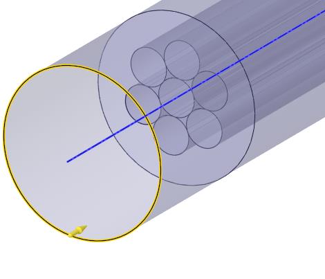
For my study, I need to construct a flow straightener (or honeycomb) with some circular straws. Currently, I have to calculate the pressure drop of my honeycomb. My staws are circular so when I gather the straws to construct the honeycomb, it creates some triangles between the different straws, and I want to use Ansys to analyze the loss caused by these triangles (encircled in red in the picture), and to determinize outlet velocities, outlet turbulence ...
I have built an example in Solidworks and import it in Ansys. I wanted to use the function "enclose" to create a box that surrounding my part (because I'm new on Ansys but I think I need it to create inlet conditions for all my part).
But I have an error message which said (I traduce French-English): " error: the operation may generate non-geometric bodies
context: geometry engine, during the generation of a function enclosure"
I didn't find any solutions on the Internet
 Could you help me, please
Edit: I tried to create a unite boolean but It doesn't work. I still have 3 bodies

Kind regards, Alex
-
March 20, 2020 at 4:19 pm
Rob
Forum ModeratorThanks for translating: I don't think my French colleagues get on here much. The error to Google is "non manifold bodies" without the " marks. You'll find a few similar threads on here too. Not quite sure how to fix this one without giving you a silly cell count.
What's the overall aim of the modelling?
-
March 20, 2020 at 9:11 pm
osmo
SubscriberThank for your help,
The overall aim of my modeling is to comparate the velocities outlet between the air thought one pipe and the air through one triangle. And also to determinize the pressure drop at the end of the triangle (because here it's a 6mm cylinder but I will compare the same structure with a 3mm cylinder).
So I wanted to create an inlet flow at the beginning of the structure ... And to my mind, I have read that I have to create a boolean and to enclose my part. But the boolean is not working. I have rebuilt my CAO to correct some tangential problems. When I want to create a boolean with add, there is the error " No overlap or wrong types".
I don't understand the meaning of overlap in Ansys
 My CAO is easy, I have only 7 cylinders and they were tangent at each other to create the structure.
-
March 20, 2020 at 9:15 pm
peteroznewman
SubscriberAlex,
Do you want air to be present in the triangle spaces, or do you want the triangles to be solid and block airflow because there is a bonding agent that fills the triangle spaces to hold the straws together?
-
March 21, 2020 at 2:43 pm
osmo
SubscriberHi,
I will construct the honeycomb with straws so yes I want air to be present. I use Ansys to measure the turbulence caused by air through these triangles.
Thanks for your help
-
March 21, 2020 at 8:55 pm
peteroznewman
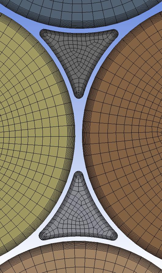
SubscriberOne way to make a good mesh is to assign a thickness to the straws. In the figure below, I made 7 straws with a 0.1 mm wall thickness. The center of the wall was at a 6 mm diameter, and the straws were spaced at a 6 mm radius, so they overlapped by half a wall thickness. I then merged the 7 bodies into a single body.
I decided that a sharp corner on the triangle will not make a good mesh. I added a blend R=0.1 mm You might decide to skip this step.
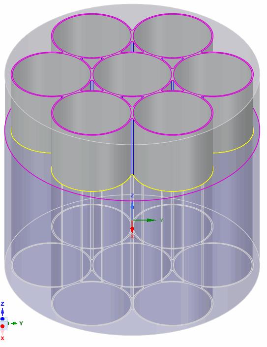
I then made a circular enclosure with this solid. Here are the Air solids...
You can easily add inflation layers to all these wall.
Good luck.
Attached is a ANSYS 2019 R3 SpaceClaim file. I can export parasolids if you are on an older version.
-
March 23, 2020 at 11:52 am
osmo
SubscriberOh ! Really nice
I will try to redo your part myself. But I don't understand some things.
In Solidworks, I have created the same structure as you. 7 6mm straws which are spaced by 6mm. I didn't precise a thickness (but to my mind it was logic ...). And I can't merge bodies to one body. So... If I understand, It's necessary to create thickness in cases like this to use some functions?
I don't understand, your enclosure, it's air?
Sorry for my misunderstanding Ahah. I will come back if I have more questions.
-
March 23, 2020 at 1:33 pm
Rob
Forum ModeratorThe thickness is to allow the volumes to unite: faces don't do that. If you're after the pressure drop you can also look at a symmetric section to reduce the cell count: find a repeating structure in the geometry: hint, it's triangular.
-
March 23, 2020 at 6:46 pm
peteroznewman
SubscriberIn Solidworks, start a sketch on the XY plane. Draw a circle 6.05 mm diameter and another circle 5.95 mm diameter. When you extrude that sketch, you will get a solid tube that has a 0.1 mm wall thickness. Copy that solid 6 mm along the X axis. Copy that copy to make the pattern of 6 solids around the center solid. You should be able to unite those 7 solids.
You could do the same operations in SpaceClaim or you could open the Solidworks part file in SpaceClaim. In either case, go to the Prepare tab and there is an Enclosure button. Select type Cylinder. The enclosure solid is the air.
-
March 24, 2020 at 1:12 pm
osmo
SubscriberThank you for your help! I'm grateful.
I finish constructing my part with a thickness. The unit worked, the same for the enclosure (I need water enclosure but I will found some tutorial to change the material inside the enclose I think) and I have created a symmetric section to reduce the cell count because my student version of Ansys cannot calculate if I have all the cells.
For the moment I tried to understand fluent so I check some youtube tutorials. The first one was to calculate velocities around my part.
Below you can see the result: My inlet velocity is 0.7 m/s and I run the compute with 60 iterations.
I have two more questions if you agree to help me.
First one, I know for the compute you have to insert several iterations and you need that the curve converges to a point. But, how it is possible to know when the curve converges and the number of iteration that I need. May I need to have a fluctuating curve to prove that my curve is converging?
And the second question. I can't explain my results. physically, I don't understand why the velocity increase in the air section. It should be constant. And to increase when air vectors enter into the canalization because ... venturi effect.
kind regards and sorry for my french-english writing ^^
-
March 24, 2020 at 5:21 pm
peteroznewman
SubscriberOsmo,
I suggest you copy your reply above into a New Discussion and put that in the Fluid Dynamics category where it will have better visibility to the CFD experts.
If you have a uniform entrance velocity, as the boundary layer develops on the walls it slows down fluid near the wall, so the fluid in the center must speed up to maintain the same mass flow rate at the end of the pipe as was entering the pipe.
This discussion can be marked as Solved if you click the Is Solution link under the post that best describes the answer to your original question.
-
March 26, 2020 at 5:21 pm
osmo
SubscriberI know this question has the solution but I have a question for you, Peter, about the design that you have created.
When I create it and I use space claim, it's working, but when I use the design modeler is different. It's easy to combine the part but after the enclosure, I don't have the same results as I could have with space claim. In space claim, when you provoke an enclosure of 0%, it creates 7 pipes and 6 triangles in the enclosure (you had changed their name to Tri-circle-solid). With this, it easier to mesh after. But I can't have the same results whit the enclosing of the design modeler... Why?
I tried your mesh and it's really better. I watched some tutorials about pressure drop in a pipe and in those tutorials, each time, you have to create an intent and an outlet in your mesh. In your design, you can't.
-
March 26, 2020 at 8:12 pm
peteroznewman
SubscriberIt is possible to create the same solid geometry at the end using either SpaceClaim or DesignModeler, they just have different tools and user interfaces. The enclosure tool is different code in each package, so it might have different results. That doesn't matter, you can use any tool available to make the air solid to look the way you want, it just depends on how much work that will be.
In my geometry, after I made the enclosure, I cut off the air solid before the straws and after the straws to make it easy to see the mesh in the straws and in the triangles. You could put the "plenum" of air before and after the straws back by simply selecting the circular edge and pulling more solid at the beginning and repeat on the other end, then you will have one inlet and one outlet. It would be best to have that be a separate solid and not merge with the 14 air solids behind it.
Another approach is to take the single face of the united 7 straws, and pull that into a solid, then pull the 14 faces of the air forward and you will have a structured mesh for the plenum. When you go to Share on the Workbench tab, make sure to type in a small Coincidence tolerance like 0.001 mm
-
March 27, 2020 at 6:01 pm
osmo
SubscriberHi Peter,
I start my file again but this time without Solidworks. I create the part in space claim to avoid some errors in the translation SolidWorks--> space claim.
So: I have the same design as you (but my internal circle is 5,95 and no 5,85). I create a circle enclosure with 3% of length. Then, as you said, a create 2 plan in the extremity of my honeycomb and I cut the part of my enclose that I didn't need.
But, I have 2 problems. Firstly, when I want to do my meshing, I can see in the folder "connections" that I have several contacts-region and not you. For each of my files, it's the same, there are many contacts regions and it's a problem when I set up fluent. Why you don't have those contacts?
The second problem, I don't know why but since I built my part in Space claim, I can't choose a manual source for the sweep mesh method, it's only automatic or automatic thin. I upload an image where you can see the two problems. I wanted to attach my file but I don't know if you are authorized to open it.
Kind regards, Alex
-
March 27, 2020 at 9:08 pm
peteroznewman
SubscriberHi Alex,
I don't think I need to open your files to help.
Delete all contacts in the Connections folder. If you use Share Topology, you don't need them.
You have to do a Sweep mesh method on only one body for the manual source face to be available then you can Inflate this method and choose the boundary edges on the selected face.
Kind regards,
Peter
-
March 28, 2020 at 12:41 pm
osmo
SubscriberHi, Peter,
I have finished the mesh, thanks for your help, but I have some misunderstanding about the creation of an inlet/outlet, sorry
 .
.
If I have understood, you select the circular edge, pull it, and you have to create another circular surface in filling the surface? What is create a circle that I can mesh and describe in fluent as the entrance of my velocity/pressure flow? Isn't it?
If yes, I have a weird problem during the meshing. Without the inlet/outlet parts, my mesh is a count of 490 000 cells. But when I add an inlet and an outlet it became 380 000 cells... It's illogical because I add more parts.
Kind regards, Alex
-
March 28, 2020 at 7:00 pm
peteroznewman
SubscriberHi Alex,
I downloaded your file, but you only put the .wbpj file in there. That file is useless without the _files folder of the same name. The proper way to share files is to use File > Archive and create a .wpbz file which is an archive of that file and folder in a single file, like a zip archive file.
I started with my Air solid file that is attached.
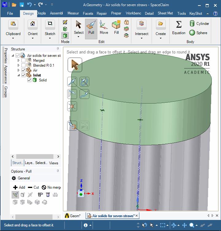
1) Create a Component called Inlet
Click on Sketch and click on the top face of the air column. Draw a circle.
Type P or click the Pull tool. Pull the surface up to the length you want for the inlet.
Click on the Workbench tab, click on the Share tool, type 0.01 into the Coincidence Tolerance box.
Repeat for the outlet end.
Good luck!
-
March 28, 2020 at 8:14 pm
osmo
SubscriberHi,
yeah it's working but I can't still use the sweep method for the meshing when I create the inlet/outlet.
Here is the archive file
Alex
-
March 28, 2020 at 9:04 pm
peteroznewman
SubscriberWith the single face inlet, you can sweep the mesh in the straws and the triangles between the straws, but you will have a tet mesh on the inlet plenum.
The previous post described how you could have 14 faces on the inlet in the same pattern as the straws and triangles, then the entire volume can be swept.
-
March 30, 2020 at 7:08 pm
osmo
SubscriberHi peter,
I have created inlet/outlet only by selecting the faces together. In fluent, I add some parameters (model : epsilon k ; cell zones conditions for solid and tri : water-liquid, boundary conditions : 0.7m.s for inlet solid and tri, 0 gauge pascal for outlet pressure, standard initialisation, 1000 iterations)
I know is not the good place to ask this question, but you know my part and step by step that I have done so :
In results, I created vectors for velocity but nothing happens. The same for contour. It's weird. Have you already seen this problem ?
Kind regards, Alex
-
March 30, 2020 at 7:45 pm
peteroznewman
SubscriberHi Alex, I'm an expert in geometry and meshing for structural models and don't know a lot about CFD. Better to ask in the Fluids category.
-
March 31, 2020 at 8:31 am
osmo
SubscriberHi Peter,
Okay I will do that Thanks again !
Kind regards, Alex
-
April 1, 2020 at 9:37 am
osmo
Subscriber
Hi Alex,
I don't think I need to open your files to help.
Delete all contacts in the Connections folder. If you use Share Topology, you don't need them.
You have to do a Sweep mesh method on only one body for the manual source face to be available then you can Inflate this method and choose the boundary edges on the selected face.
Kind regards,
I just wanted to understand perfectly the sweep method. In this post, you said that you can't use sweep mesh method with manual source face when you select more than one body.
But it is possible. In this part, it works. I tried to create a new part tallest than the first one and this time it doesn't work. I'm feeling frustrated because two same parts but one work and the other don't... illogical.
What is the "rule" behind this?
Alex
-
April 1, 2020 at 10:19 am
Rob
Forum ModeratorPeter's right, one body at a time. Occasionally it'll work as you tried, but that's more likely you were lucky and the tool ignored something (probably inflation).
-
April 13, 2020 at 9:27 am
osmo
SubscriberHi,
I try to improve mesh quality.
So I have calculated y+ for the different shapes of pipe (circular and triangle). Can you explain to me why for the circular, you used first layer thickness and why you used total thickness inflation for the triangle one?
Alex
-
April 13, 2020 at 8:25 pm
peteroznewman
SubscriberBecause I didn't calculate a y+ and was just demonstrating different ways to do inflation. Now you have a y+ you can make the inflation layers the size you need using either method.
-
- The topic ‘Problem with enclosure function for honeycomb pipe’ is closed to new replies.


-
3572
-
1188
-
1076
-
1063
-
952

© 2025 Copyright ANSYS, Inc. All rights reserved.


