-
-
February 24, 2020 at 10:46 am
Daniel97Yii
SubscriberUsing ANSYS 2019 R3, I intend to carry out four-point bending test on a RC beam. Here are the problems I encountered in the attempt to modelling and I need help with these:
1. Solver pivot warnings/ errors have been encountered during the solution. This is usually a result of an ill conditioned matrix possibly due to unreasonable material properties, an under constrained model, or contact related issues. Check results carefully...
2.A solver pivot warning or error has been detected in the UY degree of freedom of node 434 located in Line Body. This is usually a result of an ill conditioned matrix possibly due to unreasonable material properties, an under constrained model, or contact related issues. Check results carefully...
Conditions of the RC beam:
1. Beam is modelled in half, symmetry is applied to the surface normal to x-axis.
2. Mesh method: patch conforming method for concrete bodies, body sizing= 30mm for steel and stirrrups
3. Engineering properties of concrete, steel bars and stirrups are set in Engineering material (no commands added).
4. Displacement applied at only one side of the beam (since symmetry is applied), with x= free, y & z= constant to emulate simply support.
I couldn't upload the Workbench file, it says "file extension not allowed". But I attached a text file with solver output in it.
-
February 25, 2020 at 1:36 am
peteroznewman
SubscriberDaniel,
I'm guessing that the steel bars and stirrups were modeled with beam elements meshed on line bodies. How were the line bodies connected to the concrete solid body? If there was no connection, that would explain the solver pivot warnings.
There are two methods for connecting steel bars to concrete.
The first method is shared topology where you slice up the concrete block so that the edges of the slices line up with the steel bar line body. Then there is shared set of nodes along the line body that the concrete elements use as well as the steel bars. I understand how that works and have used it.
The second method is to use the MESH200 command and REINFORCEMENT commands. ANSYS will mesh the concrete body and the line body independently and somehow connect them during the solve. I haven't tried this myself.
You can't attach .wbpj files because they are useless without the _files folder. That is why you use File > Archive to create a .wbpz file that combines these into a single file that you are allowed to attach as long as the file size is < 120 MB.
-
February 25, 2020 at 3:43 am
Daniel97Yii
SubscriberI sketched the steel bars and stirrups, applied "Line from sketches", assign "circular sections" on them. Yes, they are line bodies. But I'm not sure whether they are connected to concrete.
Referring to the 2 methods you proposed, how can I implement it? Could you further break down as to how? Because I am totally new to ANSYS Workbench.
I have tried to apply "Section plane" on the beam model, only concrete is shown, as shown in the image attached.
Attached are the files for your reference (the model that I refer to is titled "C"):
Link for wbpj:
https://drive.google.com/open?id=1x-4RZ98VzHubsATlyDWA46z-wjfMlY5I
Link for _file:
https://drive.google.com/open?id=1TjrmHzidCNf9fzK2R1kBnUyGaCGdfaNr
-
February 25, 2020 at 5:45 am
-
February 26, 2020 at 10:36 am
peteroznewman
SubscriberDo a single rebar line body to learn what to do. Suppress all the stirrups and all the other line bodies.
Now you have one solid and one line going through it. Let's say the line body is parallel to the X axis.
Create a plane parallel to the XY plane that goes through the line body. Slice the solid body with that plane.
Create a plane parallel to the XZ plane that goes through the line body. Slice the two solid bodies with that plane.
If the line body is the same length as the solid body, you are done, since the solid vertices are coincident with the ends of the line body.
If the line body is shorter than the solid body, then you need a plane parallel to the YZ plane through each end of the line body. Slice all solids with each of these planes.
Now you have solid bodies that have an edge that exactly matches the line body.
In DM, you can select all the bodies and Form New Part to share topology. I can't remember if it will let you put lines together with solids.
Once you get this into Mechanical, you will not need any contact to connect the bodies, they will all have shared nodes.
You can drop a Modal Analysis onto the Static Structural model cell and add one fixed support to one face to see if the line body is connected. If you get six zero frequency modes, then it is not connected. If you get a bending mode with a real frequency, then it is connected.
-
February 26, 2020 at 11:40 am
Daniel97Yii
SubscriberHere are the section planes, looks like both the rebars and stirrups are bonded.
Bottom view of bottom rebar (other line bodies suppressed)
Bottom view of rebars and stirrups (all bodies unsuppressed)
Cross-sectional view of stirrups
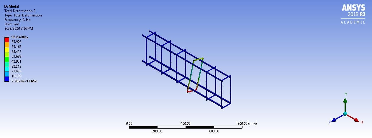
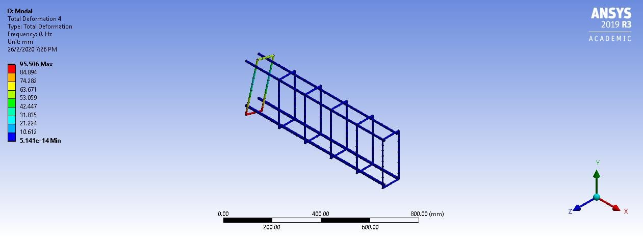
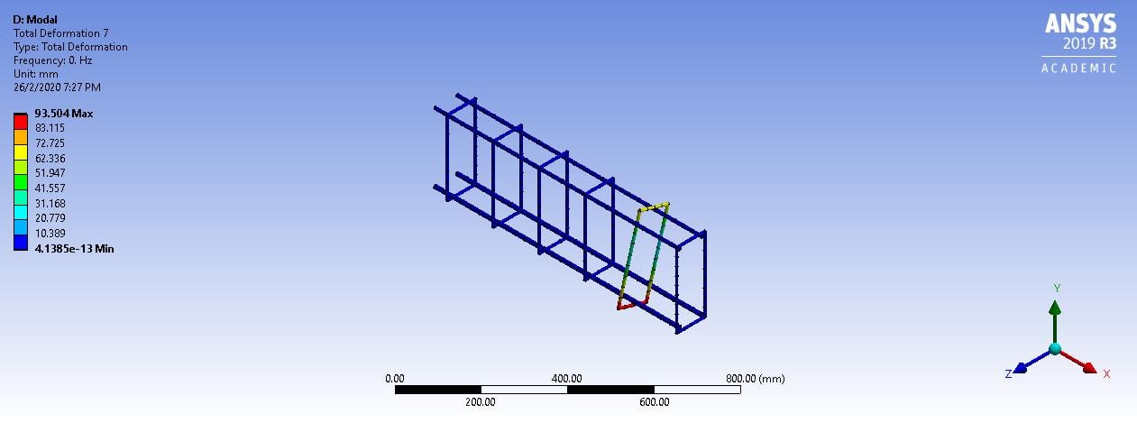
Here are the modal analysis performed, I've got 6 zero frequencies, meaning that the stirrups are not connected right? How to solve the problem?
-
February 26, 2020 at 3:14 pm
peteroznewman
SubscriberDaniel, please try what I suggested in my previous post, a single rebar.
Your model definitely has unconnected parts.
When you take section views, it is better to push the button for Whole Elements.
-
February 26, 2020 at 4:07 pm
-
February 26, 2020 at 9:06 pm
peteroznewman
SubscriberYou have not split the the concrete into four pieces along the X axis, that is why you are getting tet elements instead of hex elements.
When you have split the concrete into four pieces, you need three vertices on the line body at the planes where the concrete was sliced. I think DM has a split edge tool. But it may be simpler to use four line bodies along the path of the one line body you have now.
Does the rebar end at the end faces of the concrete? If it is inside, then you need to split the concrete at the end of the rebar.
If you open this geometry in SpaceClaim, and go to the Workbench tab, you can click on the Share button and it is easier to see if the line body is shared.
-
- The topic ‘Error: Solver pivot warnings or errors have been encountered during the solution’ is closed to new replies.


-
5094
-
1829
-
1387
-
1248
-
1021

© 2026 Copyright ANSYS, Inc. All rights reserved.


