-
-
February 23, 2020 at 8:38 pm
m.caragiuli
SubscriberHi,
I have a doubt about the contact behaviour of my system. There are two bodies that are not in contact at the beginning of the simulation, but due to a force load one should move against the other and start sliding on it transmitting the force. So I wonder if I should create the contact between the two sides (frictionless, with offset or adjust to touch?) or if I should create two steps of simulation so that in the first step one body moves until touching the other and in the second step I would insert the contact between them as frictionless to allow the relative motion. What do you think? Is this possible?
Thanks for your attention!
-
February 23, 2020 at 10:18 pm
peteroznewman
SubscriberHi nyla,
You should create the frictionless contact between the two surfaces, but edit the Pinball radius in the Details window of the contact. Type in a number larger than the initial distance between the two surfaces. It can be much larger. Surfaces are more efficient that entire bodies if you can predict which surfaces are going to be touching.
Under the Connections folder, insert a Contact Tool and Evaluate Initial Contact Status. The contact should show as Near Open. That means it will be tracked during the solution.
Without adjusting the Pinball Radius, the contact would probably show as Far Open, which means it would not be tracked and the contact condition would not be enforced when the solution moved the surfaces together.
-
February 24, 2020 at 9:42 am
m.caragiuli
SubscriberOk, thanks. Should I set as treatment interface add offset no ramped with 0 offset?
Peter, what if I have the situation represented in the following image?
I mean I have to create the contacts between the faces on the bush and pin. Since there is a gap between the bush lateral sides and the lateral sides of the pins, and between the inner face of the bush and the outer face of the pin, is it correct to assume the same approach as the one you mentioned (frictionless +pinball)? Of course there is relative motion between them and I want to avoid penetration between those faces.
Thank you for your precious tips!
-
February 24, 2020 at 3:54 pm
m.caragiuli
SubscriberHi Peter, if I set the pinball region as you mentioned during solution running warnings appear related to solver pivot such as "Solver pivot warnings or errors have been encountered during the solution. This is usually a result of an ill conditioned matrix possibly due to unreasonable material properties, an under constrained model, or contact related issues. Check results carefully." untile error occurs "An internal solution magnitude limit was exceeded. (Node Number 296057, Body splint, DOF UY) Please check your Environment for inappropriate load values or insufficient supports. You may select the offending object and/or geometry via RMB on this warning in the Messages window. Please see the Troubleshooting section of the Help System for more information." It seems that the error refers to the the translation degree of freedom along y axis. Probably one of the contacts involving body splint is not properly set. It could be one of the contacts I showed you in the image. Thus I can I fix it?
Please give me a tip since I'm adjusting the pinball region without any success.
Thanks!
-
February 24, 2020 at 8:33 pm
peteroznewman
SubscriberHi Nyla,
To solve a Static Structural model, there must be solid path from where the load is applied to ground. In the images below, the pin is attached to ground (Fixed Support) and there is a force on the ring. In the top image, there is no path to ground, there is a gap, so the solver gives you the error you saw above. In the bottom image, you have moved the ring over in CAD so it is touching and now there is a solid path to ground and the solver can converge.
Now if you had a system that supported that ring so there was a static equilibrium like the image below where there is a link on a revolute joint to the green triangle attached to ground, and a compression spring connected to the blue link and green ground, then the solver can ramp the force up and at some point, the gap will close and the orange pin will pick up the load.
-
February 25, 2020 at 8:38 am
m.caragiuli
SubscriberHi!
Please look at the following picture in which there are two configurations:
the top image refers to my starting configuration. The pins are part of the boxes (one only solid body). There is a rigid orange rod linking the two boxes. The top surface of the upper box is fixed to the ground (green line). A frictionless contact (add offset to get near open) is between the two boxes and other frictionless contacts were creted as I depicted in the previous images. A force is applied at the the pin of the lower box so that it moves the box left-and up-wards until touching the upper box in order to be transmitted (bottom figure). Maybe my problem is at the contact between the pin and the rod? I don't want them to touch since there is an offset between them. Should I use springs?
Thank you for your help!
-
February 25, 2020 at 9:53 am
peteroznewman
SubscriberFrom the starting configuration, if there was no clearance between the hole in the rigid orange link and the pin, then the lower block would move very slightly to the right in order to move up. The only reason the lower block could move to the left is because of the clearance between the pin and hole.
You say you don't want the pin to touch the hole. Is that because there is a bushing between them that fills the gap? If so, you must put that bushing in the model. If the bushing is an elastomer, then you will get some deformation in the elastomer from the applied forces.
Is the direction of the blue applied force arrow correct? You can understand that if the applied force was straight along the line of the orange link and intersected the other pin, then this force could not move the link. If the arrow pointed straight up, then it could move the lower pin up. If the pin has any friction to rotation, there is a line of force that doesn't pass through the top pin, but is within the "friction circle" of that pin, and therefore is too close to move the link up.
Is there gravity acting in this mechanism? Is this a top view or a side view? Which direction is gravity acting?
What else helps to position the lower block? In 2D, there are 3 DOF, and the orange link has taken away one. Once the lower block makes contact with the top block, that takes away two more DOF, but you can't use Static Structural to get from the starting configuration to the touching configuration. You could assemble the parts in the final configuration and do a Static Structural model to see the stress due to the applied force. Or you could have the parts in the starting configuration and do a Transient Structural model to see the parts accelerate from there and move through space due to the applied force until the parts collide and settle.
-
February 25, 2020 at 10:48 am
m.caragiuli
SubscriberHi, Thank you for the interest.
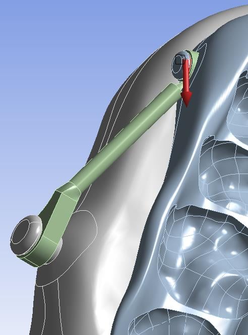
-This is a side view
-The force is applied with a tilted direction because of its Y and Z components (Y is horizontal and positive to the left, Z is vertical and positive upwards)
-there is clearance of about 0.25 mm between the pin and the inner face of the orange circle because the real model is made in this way (there is no bushing, only the pin and the circle)
- I set frictionless contact between the outer face of the pin and the inner face of the orange circlle with a pinball equal to the clearance between them
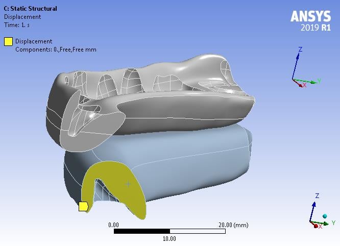
- there is no gravity force acting on the system
- the picture is a 2D representation, but the model is 3D. The lower block is unconstrained in the space but I hope that through the orange connector once I apply the force it is able to move until touching (without penetration) the upper block thus getting the stress.Â
- I appllied frictionless between the bottom face of upper block and top face of lower block so that the contact is set from the beginning resulting near open.Â
- I've also thought about assembling the two blocks in the final configurations, but they are nonplanar thus one part couls penetrate the other in some regions so I prefer to apply the force until the lower block touches in one point the upper one in order to transmit the force
- If the problem is due to the lower block can I create a two step simulation in order to create the movement of lower body until touching the upper one in the first step and then apply the force in the second step when since they touch from that moment?
Thank you!Â
Â
-
February 25, 2020 at 3:48 pm
m.caragiuli
SubscriberPeter, in the meanwhile I'm trying to perform a transient analysis, however should I leave all the settings as in the static structural? If I try to run ansys reports the following error " the body contains invalid property data. Density is required, but currentlu undefined". However in static structural I didn't defined density and got the error...
-
February 25, 2020 at 3:55 pm
peteroznewman
SubscriberThe best approach is to go into CAD and move the parts so they are tangent at the first contact point. Then you can have a closed contact and the solver will have a chance to converge with the applied force.
Transient Structural is useful if you don't know where the parts will settle, but that might have convergence problems also.
-
February 25, 2020 at 4:00 pm
m.caragiuli
SubscriberHi Peter, before going into CAD what if I set the contact between the two blocks frictional with adjust to touch? isn't that a trick to make them in contact?
In transient structuralshould I leave all the settings as in the stati structural? I've only connected the model of static to transient block.Â
-
February 25, 2020 at 4:07 pm
peteroznewman
SubscriberWhen you use Adjust to Touch, you can't control which direction the contact surface moves. It moves the shortest distance between the target and contact, but that might move the surface sideways in a way you didn't expect. You have more control in CAD. And don't you want the true geometry to be in the model, not some offset that you don't know which direction it went?
In Transient Structural, you have to set the time steps to be real in terms of milliseconds that is appropriate for the masses and forces in the model.
-
February 25, 2020 at 5:06 pm
m.caragiuli
SubscriberOk how can I understand which is the most appropriate time step?
However, if I edit the geometries in the CAD would be all the contacts defined correct?
Thank you for your tips!!
-
February 25, 2020 at 8:28 pm
peteroznewman
SubscriberIn Transient, Turn on Automatic Time Stepping. Try .001 seconds for the Initial Substep and 0.0001 for the Minimum Substep and 0.01 for the maximum substep. I expect the parts will be in place by 0.1 seconds, so that can be the End Time.
All Contacts should be created on the true CAD surface and not use Offsets or Adjust to Touch, except if the surfaces are tangent in CAD but due to discretiztion during meshing, there is a 1e-4 mm gap, then you can use Offsets or Adjust to Touch to close that gap.
-
February 26, 2020 at 8:23 am
m.caragiuli
Subscriberok about the Transient structural settings. However, my contacts involve bodies which could come in contact during motion since at initial configuration there are clearences between all the bodies. So I'm setting frictionless with pinball radius a little bit larger than the gap to make them near open as you suggested me. Is it ok?Â
the following picture explains better the contacts I plan to set by identifying them using different colours (only upper block is shown since the lower one has the same contacts)
Thank you very much!
-
February 26, 2020 at 9:14 am
peteroznewman
SubscriberThose are a good set of contacts. The pinball radius is very different from an offset in the contact. Take contact #4 for example. A large pinball is required so that the solver finds the contact Near Open so that it pays attention to it from the beginning. Without that the contact might have a Far Open status and the dynamics will take the blocks through each other during the solution. If a positive offset is used and the contact is Near Open, then the blocks will make contact at the offset distance and when they come to rest, the blocks will be separated by the offset distance.
-
February 26, 2020 at 10:35 am
m.caragiuli
SubscriberThank you very much! Now, I'm running the transient simulation even if it takes a lot of time. I'll update you about the Transient analysis as soon as it ends. Thanks a lot for now!
-
February 26, 2020 at 11:46 am
m.caragiuli
SubscriberHi, just a question... what does it mean if a frictionless contact become closed in initial status? I set pinball in order to have near open, but after simulation it became closed with a slight penetration.Â
-
February 26, 2020 at 9:38 pm
peteroznewman
SubscriberAny contact that is closed during the evaluation of the initial status is good unless the penetration is excessive.
The pinball radius is used to convert a far open status to near open. It does not close contacts. Adjust to touch can convert a near open to closed.
-
February 27, 2020 at 12:37 pm
m.caragiuli
SubscriberHi Peter,
Thanks for the tips! Transient structural doesn't work, thus I'm simulating the model by editing the CAD on order to make the two blocks in contact at least in a point.
However, I want to know from your expertise if it is possible to run a simulation of the two blocks slightly separated in order to give them the displacement required to get in contact and use the output (bodies in contact) as input for a new simulation where I apply the force.
To be clearer I think to do that because I need to change the contact between the two blocks: they are initially few millimiters apart from each other thus frictionless contact fits correctly, then at the end of the simulation they should touch in a point and I want to use that configuration as input for a second simulation in which the contact between the two blocks becomes no separation since they can slide and I'm able to apply the force to be transmitted.Â
Do you think is it possible? If it is, is there a way to tell Ansys to stop the first simulation as soon as the two bodies touch, so I am sure that they are in contact without penetrating each other?
Hope to receive your opinion since I'm quite interested in that!
-
February 27, 2020 at 1:29 pm
peteroznewman
SubscriberIt is best to move the parts to be just touching in CAD. It is okay if the parts are slightly penetrating in CAD.
Either way, use contact and apply the force in the simulation. It is best to have a small friction coefficient (0.05) to help stabilize the solution. Why do you think the surfaces are frictionless?
The solver will iterate the degrees of freedom in the model to find an equilibrium. This includes pushing the bodies apart if there was some small initial penetration left in the CAD model. There is no need for two steps or a first and second simulation.
-
February 27, 2020 at 3:54 pm
m.caragiuli
Subscriber- simulation diverges if I apply the force when considering the blocks as separated (frictional or frictionless provide the same error) due to a internal magnitude exceeded. It seems it is not well constrained. This is why I was thinkg about a two steps procedure (Should I create a new discussion to get some information about the feasibility of a two steps simulation where the output of the first simulation are used as input for a new simulation?)
- if I move the blocks in the CAD to make them touch at least in a point the simulations works (I used no separation as contact since they can slide one on the other and they touch in a point, moreover frictionless or frictional don't work in this case) but it seems that the force is not transmitted by the lateral connection, only by the contact surface
-In previous simulations I assumed the contact between the two surfaces as frictionless because I don't know the actual friction that can occur, moreover the environment where the blocks are is lubricated thus I thinks I can assume no friction.
-
February 27, 2020 at 6:13 pm
peteroznewman
SubscriberDon't spend time solving in Static Structural if the blocks are separated unless Step 1 uses displacement to move the blocks to be touching. But why do that in the solver when you can do that in CAD?
Don't use No Separation, use Frictional Contact with 0.05 coefficient. Though the first attempt with Frictional contact failed to converge, there are many adjustments that can generally result in convergence. Please show your Analysis Settings. What were the Initial Substeps? What was the error message when the solver stopped?
Lubricated is not frictionless. It is a small friction.
If you want to share your model you can use File Archive and attach a .wbpz file to your reply. Say what version of ANSYS you are using.
-
February 28, 2020 at 12:18 pm
m.caragiuli
SubscriberTrying to run the simulation with frictional contact between the two bodies in contact at least in a point,
I get the following errors:
Â
An internal solution magnitude limit was exceeded. (Node Number 19745, Body MAD inferior splint(frictional between two splints), DOF UY) Please check your Environment for inappropriate load values or insufficient supports. You may select the offending object and/or geometry via RMB on this warning in the Messages window. Please see the Troubleshooting section of the Help System for more information.
An internal solution magnitude limit was exceeded. Please check your Environment for inappropriate load values or insufficient supports. Please see the Troubleshooting section of the Help System for more information.
Analysis settings are the following:
initial substeps 10
minimum substeps 10
maximum substeps 20
(I've tried also 20,20,40 but same error occur and computational time increase)
solver: direct
large deflection: on (it I set as off I get the error "Â unconverged solution" after 20 minutes of simulation)Â
Â
If I switch the frictional to no sepration I get convergence but the lateral link connecting the two blocks doesn't transmit the force in the upper region.
-
February 28, 2020 at 1:27 pm
peteroznewman
Subscriber0) Add a Modal analysis and drag the fixed or zero displacements from the static structural down to the Modal. Request 12 modes. What is the frequency of the first 6 modes is it almost zero? Look at the mode shape, what part is moving? You might have to adjust the display scale to see it properly. Use Animation.
1) Under the Connections folder, insert a Contact Tool and Generate Initial Contact Status. Reply with the table of results. Are all the contacts closed?
2) You can try Initial Substeps 1000, minimum substeps 10, maximum 1000.
3) You can try a 2-step solution. In step 1, the force is zero. this is just to let the contact establish. In step 2, the force is on and the initial substeps are 1000.
4) You can turn on Weak Springs under the analysis settings.
5) What does a deformation plot of the unconverged solution show?
Â
-
February 28, 2020 at 1:59 pm
m.caragiuli
Subscriber Hi Peter, I'm not able to attach the archive since it is very heavy 2 Gb, also by clearing the data. What can I do?
In the meanwhile I can share this plots:
this about the contacts
this about the plot of deformation during divergence (the lower block disappered!)
and is displayed a CE figure at the lateral arm, I don't know why..
-
February 28, 2020 at 2:14 pm
m.caragiuli
SubscriberI've done a modal analysis by connecting the model of my Static structural to the model of modal analysis and I launghe the simulation requiring 12 modes. This is the output
To see the motion of the part I inserted total deformation, this is the output
 actually the first 6 frequencies are near zero as you asked me, what does it mean? How do you know haow many frequencies I should input?
the part moving is the lateral arm
Â
-
March 1, 2020 at 12:43 pm
peteroznewman
SubscriberYou have six contacts that are Near Open, so there is no connection for a Static Structural model to hold the parts together, and in Modal, a part will float away.
The gaps are between 0.12 mm and 0.68 mm. You must move the parts in CAD to have the contacts be closed, even if there is a slight penetration.
Friction will help the solver get started if not all six contacts are closed, you are still using Frictionless.
Was the archive 2 GB after clearing the Mesh? If so, you can share by uploading the archive to your Google email to generate a link that you can put in your reply with the version of ANSYS you are using.
-
March 2, 2020 at 9:02 am
m.caragiuli
Subscriberhttps://drive.google.com/file/d/1BmK5AW3WrNgpugw9Cg4GC0GPfpgSavSB/view?usp=sharing I'm using Ansys Workbech 2019 R1
Now I have edited all the contats according to what you told me. Error persists. Thanks for all!
-
March 2, 2020 at 3:05 pm
peteroznewman
SubscriberIsn't this a half model? I added a Symmetry BC like this.
Turned on Weak Springs to mitigate the Near Open Contact Tool Initial Results.
You didn't move anything in CAD to close the gaps. You must move the parts in CAD until the boss/head is touching the hole/face of the rigid link on both ends. Since there is clearance, only one face can touch. Due to the direction of force, the green part will push on the bone side of the dark grey part and the other end will push on the boss side of the light grey part.
-
March 2, 2020 at 3:12 pm
m.caragiuli
SubscriberYes, it is half model, me too I've added a symmetry region in the model block (lateral face of both the splints not only the lower one as you did), I've noticed that if I open the mechanical model block there is the symmetry region, but if I open the static structural block the symmetry is not considered. However, I've moved on the CAD only the two splints to be in contact and they are since the contact results closed. But all the other six contacts are near open because I didn't moved them since you said that friction can be suitable too.Â
Â
-
March 2, 2020 at 3:30 pm
peteroznewman
SubscriberFriction helps when some of the contacts are closed. None of the contacts are closed. Move the parts as described above.
-
March 2, 2020 at 4:45 pm
m.caragiuli
SubscriberI will do that and let you know. Thanks!
-
March 3, 2020 at 10:17 am
m.caragiuli
SubscriberHi Peter, I can show you the results of this new simulation where I moved everything into CAD in order to make the contact surfaces touching. Here is th elink to the archive  https://drive.google.com/open?id=1LeVzshuAcWbK0Y9ilyj8j2SXO4gkCgPu.Â
All contacts are closed except one that is near open, but I used a large pinball. However, I checked the status usign the contact tool and contact surfaces result to be "near" whilst should be sticking I think or at least sliding, why?
Moreover, I don't agree with the displacement of the lower body which should go upwards and backwards, whilst it seems to detach (from 0,05 on). Moreover, there is a large stress in correspondence of the lower pin and I have noticed that the stress appears suddenly at about time 0,05 and later it seems to not spread in the surrounding regions as I expect.Â
Can you have a look at the model please?
Thanks again for all your help and time!
-
March 3, 2020 at 9:49 pm
peteroznewman
SubscriberHi Nyla,
You use the words "lower body" and "upwards and backwards", but that only makes sense if I am looking at the model from the same direction as you. In the model there is a superior and inferior body and directions +Z and +Y. You should use these terms as they are unambiguous.
With Z axis up, the superior, which is Fixed, is on the top of the inferior. The force is on the inferior and pushes it in the +Y direction, which I think is what you mean by "backwards".
Since the line of action of the force is below the angle of the rigid link, I expect the lower body to move downward (-Z) and it does.
I also don't think the force should be on the post. The force is applied elsewhere. The post picks up the contact force from the rigid link.
-
March 4, 2020 at 9:46 am
m.caragiuli
SubscriberHi, you're right, I'm sorry. I must be precise and careful about the reference system. What do you mean by your last observation?Â
In order to get a sliding motion between the inferior and superior blocks without separation do I need to change the direction of the force above the angle of the rigid body or it is better to switch the frictional contact between the blocks to no separation? The force thus the stress should interests not only the region surrounding the pins but also the socket of the teeth while it seems that the stress is uniform all over the two blocks. I expect regions of less stress for exemple at the teeth pockets near the simmetry region and higher stress near the pins.
Thanks a lot!Â
-
- The topic ‘contact settings’ is closed to new replies.
-
3582
-
1193
-
1086
-
1063
-
952
© 2025 Copyright ANSYS, Inc. All rights reserved.