-
-
January 29, 2020 at 6:44 pm
mhmaz
SubscriberHi,
I want to simulate RCS of a structure when illustrated by a circular polarized plane wave. In the software, it only give the RCS for linear polarized plane wave. When I change the excitation to circular pol, there is no Monostatic RCS result in the results tab after the simulation. Can you please help me with this issue?
-
February 1, 2020 at 1:05 am
ssingh
Ansys EmployeeHello,Â
Unfortunately, software is programmed to report RCS with linearly polarized plane wave. But, you can assign circular polarization either by assigning single incident wave, selecting elliptical polarization , considering polarization angle equals to 90 and Polarization ratio equals to 1 as shown in the figure 1 or you can assign two incident waves with same magnitude and a 90 degree phase shift as shown in figure 2 &3 to still calculate RCS based on the far field from the point directed from the scatterer and the incident field.Â
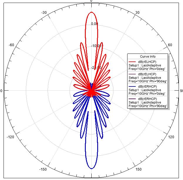
As shown in the attached formula, you will get the RCS in this case. Also, you can plot rE LHCP and RHCP to verify that upon sending the circular polarized incident wave, you can see the scattered field is also circularly polarized. In this example, i created circularly incident wave propagating in positive z direction and reflected at theta = -180 degree. Please try and let me know if you have any questions.Â
Kind Regards,
Sahitya
Â
Â
-
February 10, 2020 at 8:53 pm
mhmaz
SubscriberHi Sahitya,
Â
Thanks to your response. I tried using one plane wave with circular polarization and then converting the rE to RCS. According to the formula, by adding 10*log(4pi) to the dB(rE), we can get the RCS in all cases, assuming |E^i|=1.
I wanted to validate this technique with linear polarization, since HFSS gives the monostatic RCS with linear illumination. However, I found that the two values are not the same at all. The dB(rEX) is always higher than the dB (RCSX) when illuminated by Y polarized wave. Can you please advise?
Â
Regards
Mohammad
-
April 28, 2020 at 6:36 am
EM2020
SubscriberHi Sahitya,
Â
I followed your suggestion. I simulated at 10 GHz with 200mm by 200 mm full copper. Plane-wave is in z-direction.
With full copper plate, wave should reflect back in -z direction.
But why the radiation pattern of LHCP and RHCP are different? it seems that wave can pass through copper plate.
Â
-
January 1, 2021 at 7:44 pm
kydz
SubscriberHi,nI read this discussion and it is very help me about my problem. Thank you a lot. But i want to ask different question about this situation.nIn my problem, i want to plot monostatic RCS for different theta incident angle (0:20:180 degree, total of 10). Instead, HFSS rE plot 10 different theta incident angle for every radiation sphere resolution (0:2:180). So, this means that it is plot bistatic RCS.nI set the incident plane wave as elliptically polarized (90 degree and 1 ratio for RHCP polarization).nIs there different way to plot Monostatic case? Can you help me please about this situation? Thank you a lot...n
-
- The topic ‘RCS circular polarization’ is closed to new replies.
- Y wiring method and the start and end points of winding.
- Lumped Port Deembed
- Hfss 3D pcb via capped and filled with epoxy
- Optimizing Via Impedance in Ansys HFSS 3D Layout Using Geometric Parameter Sweep
- AEDT Natural Convection with default correlation is failing solver initializatio
- HFSS libnvidia-ml.so too old or could not be found – Warning in slurm job output
- Three-Phase Voltage Imbalances in dual stator electric generator
- STL Import Errors in HFSS After Cleaning in SpaceClaim
- Calc Error in Field Calculator after PyAEDT Analyze
- import file autocad 3d
-
3862
-
1414
-
1220
-
1118
-
1015
© 2025 Copyright ANSYS, Inc. All rights reserved.