-
-
January 6, 2025 at 5:14 pmjingyuliuSubscriber
Hi,Â
Â
I am currently conducting simulations to analyze fluid-induced noise in a T-junction pipe using the Computational Aeroacoustics (CAA) method. The turbulence model employed in the simulation is LES, with the WALE model as the subgrid-scale model.
In my simulations, the working fluid is gas, and I have tested two scenarios:
- Compressibility considered: The compressible fluid option was enabled, incorporating the bulk modulus of the gas.
- Compressibility not considered: The fluid was treated as incompressible.
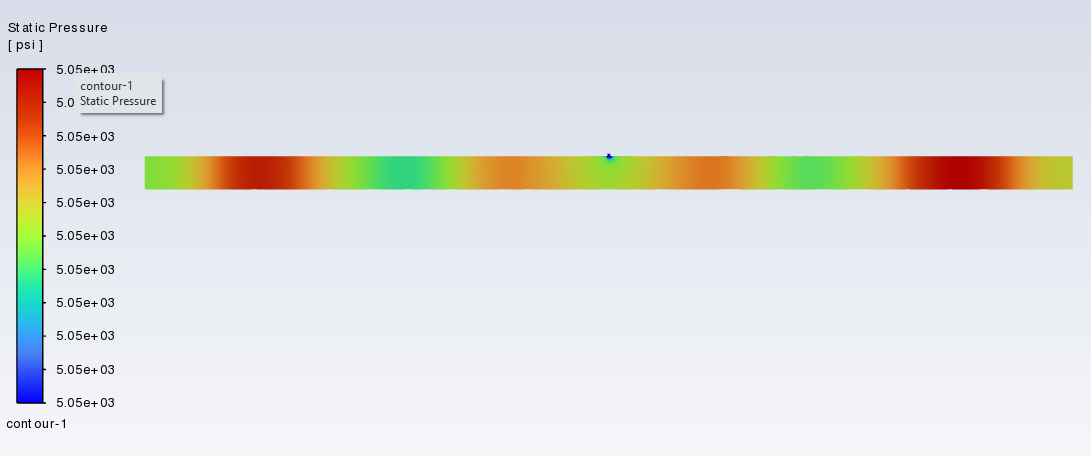
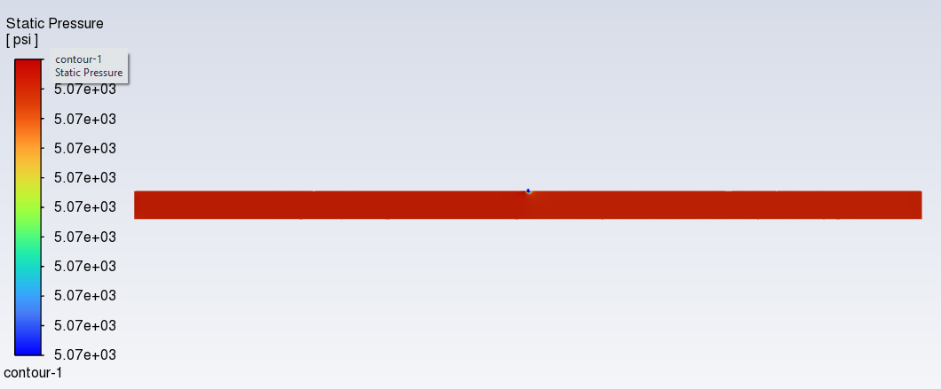
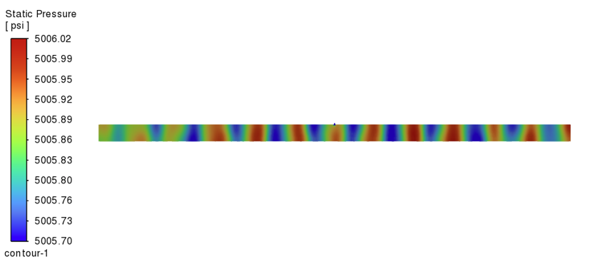
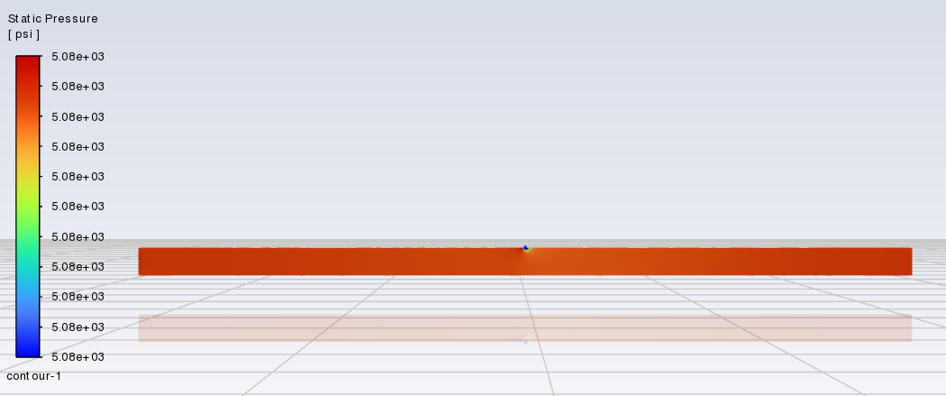
The results of these two scenarios show a significant difference. Specifically, when considering compressibility, the simulation exhibits large oscillations. I am uncertain which result is more accurate or if this difference is expected due to the nature of compressibility effects.
here is the result:Â Â
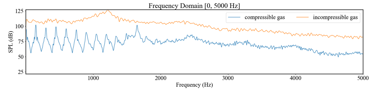
To further investigate, I have also used different gas materials, including Peng-Robinson methane and NIST methane models. However, the results remain consistent with those obtained from the compressible gas simulation, showing similar oscillatory behavior.
I would appreciate your insights on whether the large oscillations in the compressible fluid case are physically reasonable or if there might be an issue with the modeling approach. Additionally, any suggestions for further validation or adjustments to the simulation settings would be greatly helpful.
Thank you for your time and assistance. I look forward to your feedback.
Jingyu Liu -
January 13, 2025 at 3:40 pmFedericoAnsys Employee
CAA analysis requires a time accurate, compressible, turbulent, scale resolving CFD flow solution. All acoustic frequencies of interest must be spatially and temporally resolved from the source to the receiver location.
Although we cannot say from this SPL plot alone whether these results are physically reasonable, you may be seeing some feedback/resonance in the compressible results that will not be captured with an incompressible fluid.
You may show pressure-contour plots for us to better understand your model and results.
-
January 13, 2025 at 9:51 pmjingyuliuSubscriber
Â
Thanks for your reply.
The model i use is a pipe with a leakage.
here I show two set of pressure distriution from the water fluid test and gas fluid test.pressure contour of compressible fluid of water
Â
incompressible fluid of water
pressure contour of compressible fluid of gas
incompressible fluid of gas
Â
The resonance for the compressible water is clear. Â
Â
-
January 20, 2025 at 2:26 pmFedericoAnsys Employee
I agree, those are clearly visible in the compressible fluid results that you show.
-
-
- You must be logged in to reply to this topic.
- How do I get my hands on Ansys Rocky DEM
- Non-Intersected faces found for matching interface periodic-walls
- Unburnt Hydrocarbons contour in ANSYS FORTE for sector mesh
- Help: About the expression of turbulent viscosity in Realizable k-e model
- Script Error
- Mass Conservation Issue in Methane Pyrolysis Shock Tube Simulation
- Facing trouble regarding setting up boundary conditions for SOEC Modeling
- convergence issue for transonic flow
- Running ANSYS Fluent on a HPC Cluster
- Point exception in erosion calculation
-
1882
-
802
-
599
-
591
-
366
© 2025 Copyright ANSYS, Inc. All rights reserved.