-
-
January 17, 2020 at 6:40 pm
-
January 17, 2020 at 9:58 pm
peteroznewman
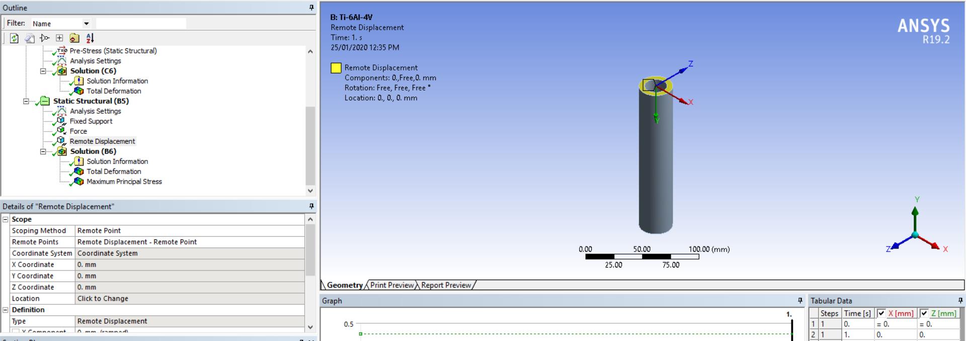
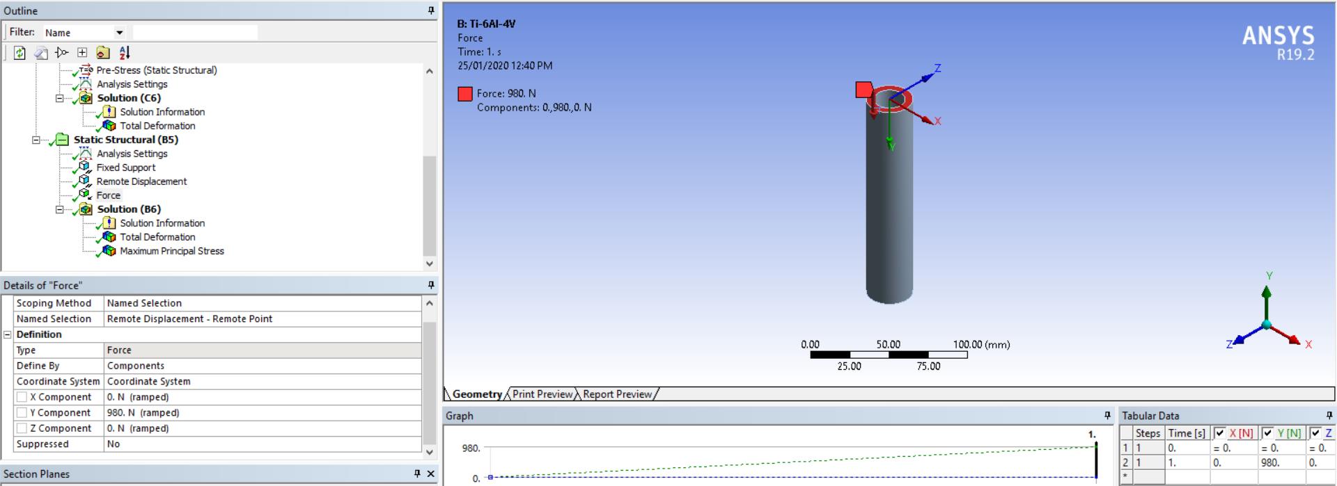
SubscriberDelete the displacement and use a Remote Displacement. Now promote to a Remote Point. On the Remote Displacement, fix X and Z to 0 leaving Y free and the rotations free. That is a pinned end. You could set Rot-Y and Rot-Z to 0 and then the pin axis is the X-axis. Apply the buckling Y component force to the Remote Point. -
January 18, 2020 at 4:44 pm
erika15
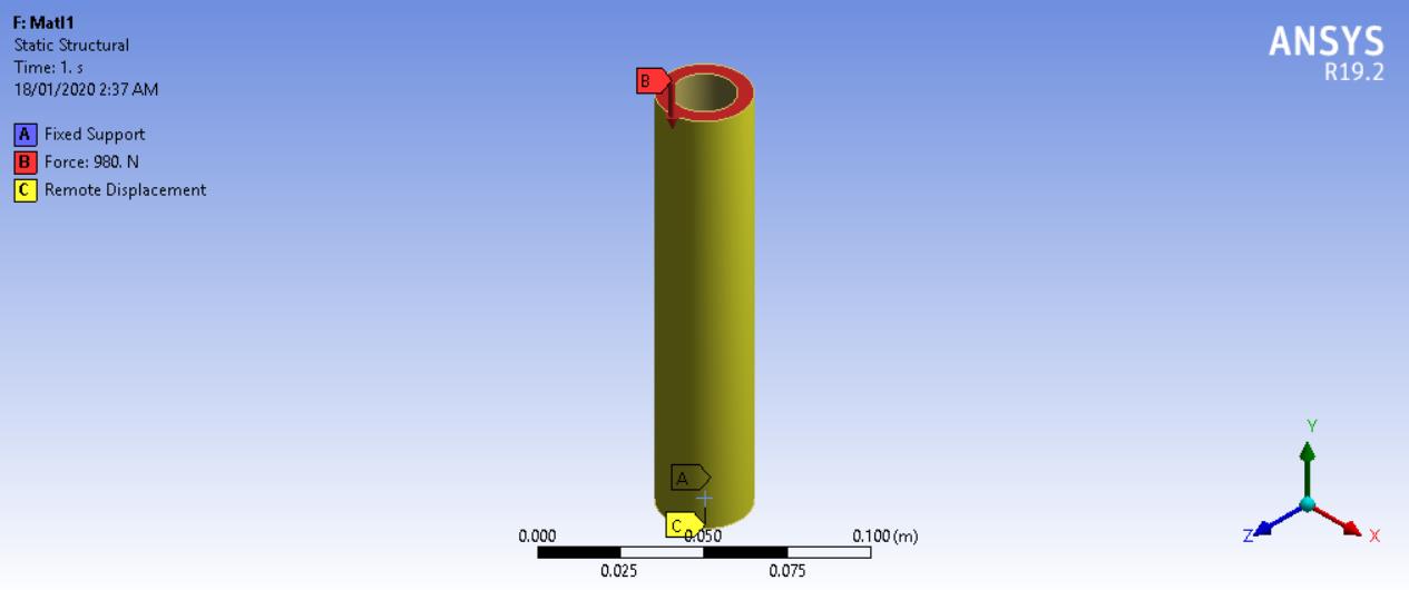
SubscriberThank you very much for the help! I'm not sure if I.'m doing it correctly though. I used remote displacement and promote it to remote point. On the remote point, I selected the top face of the model.
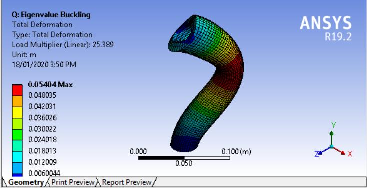
I then applied the force onto the remote point (which I made into a named selection), and got this result. I'm not sure if this is what it should look like.

-
January 18, 2020 at 10:15 pm
peteroznewman
SubscriberThat is normal. There is a Result scale factor in the ribbon that you can change to reduce the exaggerated deformation. The important part of the result is the Load Multiplier. That is what you multiply your applied load by to get a linear estimate of the buckling load. -
January 20, 2020 at 6:35 am
erika15
SubscriberThank you very much! You are a big help!
-
January 25, 2020 at 4:43 am
erika15
SubscriberHi, I'm still having problems regarding the result of the simulation. Comparing the buckling critical load I got from the simulation and the one I calculated, there is a 20% error in their values. I'm not sure if I have done something wrong in doing the remote displacement support or the force application.


-
January 25, 2020 at 4:18 pm
peteroznewman
SubscriberThe equation you used for the hand calculation might have simplifying assumptions built-in, such as Euler beam theory, while the ANSYS model is not using the same simplifying assumptions. The agreement of 20% is adequate to show that you have not made any significant mistake such as using the wrong units in a material property, for example, which could result in an order of magnitude error.
-
- The topic ‘Fixed-pin connection in buckling’ is closed to new replies.


- The legend values are not changing.
- LPBF Simulation of dissimilar materials in ANSYS mechanical (Thermal Transient)
- Convergence error in modal analysis
- How to model a bimodular material in Mechanical
- APDL, memory, solid
- Meaning of the error
- Simulate a fan on the end of shaft
- Nonlinear load cases combinations
- Real Life Example of a non-symmetric eigenvalue problem
- How can the results of Pressures and Motions for all elements be obtained?

-
3912
-
1414
-
1256
-
1118
-
1015

© 2025 Copyright ANSYS, Inc. All rights reserved.


