-
-
January 5, 2020 at 6:00 pm
levinz95
SubscriberHi everyone! I'm a mechanical engineering student and I've problem with this warning.
"not enough constraints appear to be applied to prevent rigid body motion. this may lead to solution warnings or errors. check results carefully."
The model is the boom of an excavator: in target D and E there are the connections to an hypothetical chassis; in target A there is the pin which connects the piston and the boom and permits the rotation. I put the constraints in order to create a three-hinged arch, so I chose the cylindrical supports to recreate the revolute joints (target A, D, E in the figure), blocking axial and radial directions and freeing the tangential one, but it didn't work: "Not enough constraints ..."
So I tried another way: I created two cylindrical coordinate systems, one in target D the other in target E, and I put diplacements like in the figure below, blocking the translations and freeing the rotation, but the problem persists.
-
January 5, 2020 at 10:05 pm
peteroznewman
SubscriberWithout seeing another view, I assume that the green structure is two plates connected, so that there are two holes at D, one on each side of the piston hole at E.
How you model this depends on whether you want accurate stresses around the holes at D. A simple way to model this is to use joints to ground at each hole. This is a little less accurate than using a Compression Only Support which would allow the force to go to one side of the hole, while a joint will distribute the force all around the hole (tension and compression), which is less accurate. If you use two spherical joints to ground at the two holes at D, that will take care of the green part.
A spherical joint to ground at E will keep the hydraulic cylinder with adequate support since the other end A has a cylindrical support.
You might still get a warning, but if the solution looks good, then you can ignore the warning.
A troubleshooting method is to drop a Modal analysis on the Static Structural Model cell and solve the Modal to see if the parts stay connected.
-
January 6, 2020 at 5:36 pm
levinz95
SubscriberThanks for your reply. The first image below shows a better view of the structure and the displacement constraint: I selected the two internal faces of the holes which support an hypothetical pin that connects the boom to the chassis, freeing the Y rotation and blocking the X and Z translations (same story for target E, selecting the internal face of the hole in the cylinder).
The cylinder has been modeled as a rigid rod (so there's no chamber for the working fluid, but this is a full body, Figure 2) in order to create the three-hinged arch, so I can't understand why Ansys gives me the "Not enough constraints ..." warning everytime (the selected face for the cylindrical support is the external one of the green pin, target A).
I also tried to launch the analysis adding some joints in the section "Connections": revolute joints in target D and E (Connection type: body to ground) and revolute joint in target A (Connection type: body to body as in figure 3), but Ansys shows me a warning about "Large deflection" that should be ON and the "Not enough constraints.." one.
The last figure shows the results with the "not enough constraints.." warning: they seem coherent, but the moment reactions in D and A are very high (the order of magnitude is e+005). D and A are two hinges, so I don't expect a moment reaction.
I can't understand where I went wrong.
-
January 7, 2020 at 4:31 am
peteroznewman
SubscriberThe mistake is that you have created a cylindrical coordinate system and have set a 0 constraint on the Y-component of the cylindrical csys. The X component is Radial and the Y component is Tangential. The first image above shows Radial is Free, but that is not what you want, you want that to be 0. Setting Tangential to 0 prevents rotation, when you actually want that to be free.
Another suggestion is to use symmetry if your load is symmetric. You have a section view, but if you go back to CAD and slice the geometry on that symmetry plane, you can use a Symmetry Region. That means all the cut faces will have Z=0 displacement boundary condition. That takes away 3 Degrees of Freedom, making it easier to constrain the parts. Now it will be easy to put a Compression Only support on the one hole at D. If you cut the geometry in half, you also have to cut the applied force in half to have the same stress as the full model with the full force.
-
January 8, 2020 at 3:04 pm
levinz95
SubscriberThank you peteroznewman. I thought I was working with radial and axial equal to zero and tangential free, but you got me see that my conditions were wrong.
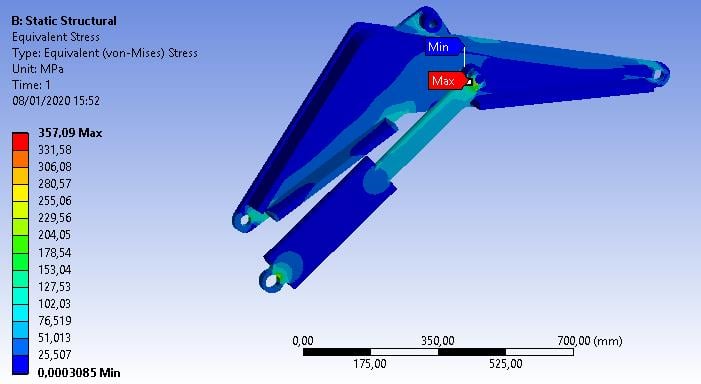
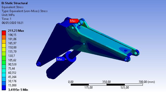
Anyway, I think I solved my problems. In the old target A I made two slices of the pin which blocks the cylinder, in order to create three different patches of the external pin surface: I put a body-to-body FIXED joints between the extremal parts of the pin and the lateral plates, and a body-to-body REVOLUTE joint between the attack of the cylinder and the middle part of the sliced pin. Now, this is a fully-fledged internal hinge of the three hinged arch and no more a cylindrical support, which links the body to the ground and doesn't enable the blue part of the body to react to the loads! In fact, in the first simulation the cylinder is blue, but it shouldn't be blue, because it MUST HAVE a reaction directed along the axis of the cylinder.
After that, I put two displacements in cylindrical csys (but it's the same putting two cylindrical supports) in target D and E, blocking the axial and radial directions and freeing the rotation. Now, these constraints link the boom and the cylinder to the ground, in fact the old blue part of the boom is now reacting to the force applied.
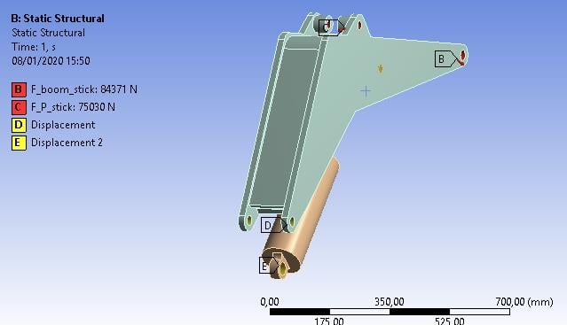
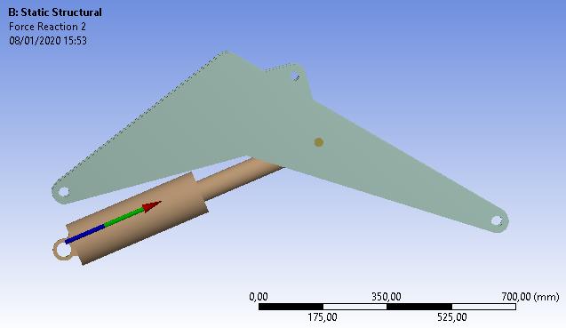
I made a further check: I put moment and force reactions probe in D and E. Moment reactions are little more than zero (about 1Nm) and it's correct because the hinge constraint has no moment reaction; force reaction in E is now axial and it's also correct, because the cylinder works in traction or compression, so the reaction must be axial, and this is verified.
The "not enough constraints .." warning still appears, but I think the results are coherent, aren't they?
-
January 9, 2020 at 2:42 am
peteroznewman
SubscriberThat looks better.
-
- The topic ‘“Not enough constraints…” problem with the excavator’s boom’ is closed to new replies.
-
4989
-
1665
-
1386
-
1242
-
1021
© 2026 Copyright ANSYS, Inc. All rights reserved.


