-
-
December 24, 2019 at 9:33 am
Jmc79
SubscriberHello I am new in ansys and in my postgraduate project I try to model the thermal expansion in a seven cylinder model with the one inside the other and where every cylinder has a different material properties!! Whatever I try the results are not the expected in the z normal strains as if I model one cylinder with the properties of a combine material! -
December 24, 2019 at 2:33 pm
peteroznewman
SubscriberAre you using an axisymmetric or a 2D plane strain model?
Please use the Insert Image button to show some screen snapshots of your model.
-
December 24, 2019 at 5:06 pm
Jmc79
SubscriberAxisymmetrc 3D
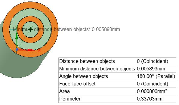
In design I draw 7 cylinder (one inside the other r1<><><><><> -
December 24, 2019 at 6:32 pm
peteroznewman
SubscriberWhat result did you get, what did you expect?
If you use File, Archive to create a .wbpz file, you can attach that after you post so I can see your model.
-
December 24, 2019 at 8:24 pm
Jmc79
SubscriberI model the composite material as a seven concentric cylinder where the body between every two cylinders are from diferent material.
Spefifically the first cylinder is fiber material the space between the first and the second cylinder is interface material next matrix,next interface again next filler ,interface and finaly matrix.
In design i draw the 7 cylinders and then seperate them so to have the seven bodys .Next i put them in a new component.
I put in one side of the model fixed constrain and give thermal load from 20 to 100 celsious.
I want to take the normal strain z so as to calculate the young modulus for diferent steps of temperature from 20 to 30 next to 40 etc.
When i try one cylinder with properties as a combine material from the filler - matrix - interface (for the specific percentance of each one) the results where ok with my theroritical analysis.
But with the seven phase model i cant have good results because my model dosent give me a resultant strain.I think that dosent see the seven phase model as one compact body.
-
December 25, 2019 at 4:09 am
peteroznewman
SubscriberYou didn't say what version of ANSYS you are using. I worked in 2019 R1. If you are using an older version, you will not be able to open the attached file.
I moved your geometry so the axis of symmetry was along the Y axis instead of the Z axis. Then I used two planes to cut the cylinders into 1/4 cylinders, then I copied the radial faces in the XY plane off the 7 cylinder solids and pasted those faces into SpaceClaim. Finally, I deleted all the solids and set these surfaces up with Shared Topology.
Next I started a Static Structural model, and set the Geometry cell to 2D in Workbench before I opened the model.
In Mechanical, I changed the analysis type to Axisymmetric, where the Y axis is the axis of the cylinder and only the radial slice along the X axis is shown. I set the bottom of the structure to have a displacement of Y = 0 to constrain the model.
You didn't provide the materials, only the geometry, so you will have to create or export/import the materials you used and assign them to the bodies.
-
December 25, 2019 at 8:16 am
Jmc79
SubscriberThanks for your response i try to run your model and it seens that again didnt solve it as a one body.
In the results every domain have its own strain due to the difference in thermal expansion coefficient a.
The treory says that if two or more materials which are connected together have a thermal load the one with less ( a ) will expand less than if it was alone for the same thermal load and on the other hand the material with bigger (a) tends to expand more than if it was alone.
In the results of your model i have this problem
I cant see the strain as result of one body.
This was the problem with my 3d model too.
I fill the materilas properties and i attach the file.
-
December 25, 2019 at 8:29 am
Jmc79
Subscriberi cant attach the file
the materila propeerties are
bond (interface): density 1,2 gr/cm^3 , E=2,2546E+10, pois=0,268, isotropic thermal coeff. expansion=2,4E-6 at 20 celsious
cylinder 1 and 3 (fiber): density 2,55 gr/cm^3 , E=7,2E+10, pois=0,2, isotropic thermal coeff. expansion=5E-6 at 20 celsious
cylinder 2 and 34(matrix): density 1,2 gr/cm^3 , E=3,5E+9, pois=0,35, isotropic thermal coeff. expansion=5,2E-5 at 20 celsious
I have as reference poit 20 celsious and i give thermal load to 100c
Thank you a lot for your help
-
December 25, 2019 at 3:22 pm
peteroznewman
SubscriberYou can only attach a short list of file extensions. You can't attach a .wbpj file because it is useless without the _files folder of the same name. You can attach a .wbpz file because that contains both. You create that file by using the File, Archive menu in Workbench. When you do that, make sure to say what version of ANSYS you are using.
Below is the axial displacement of the top of the tubes with the bonds suppressed. You can see the radial slice of the cylinders 1 2 3 4 from left to right.
Below is the axial displacement of the top of the length with the bonds working.
The Modulus ratio of Cyl13/Cyl24 is about 20
The CTE ratio of Cyl13/Cyl24 is about 0.096
The Area ratio of Cyl13/Cyl24 is about 0.69
-
December 25, 2019 at 10:23 pm
Jmc79
SubscriberHello.
I run your model and it seems that dosent work again.
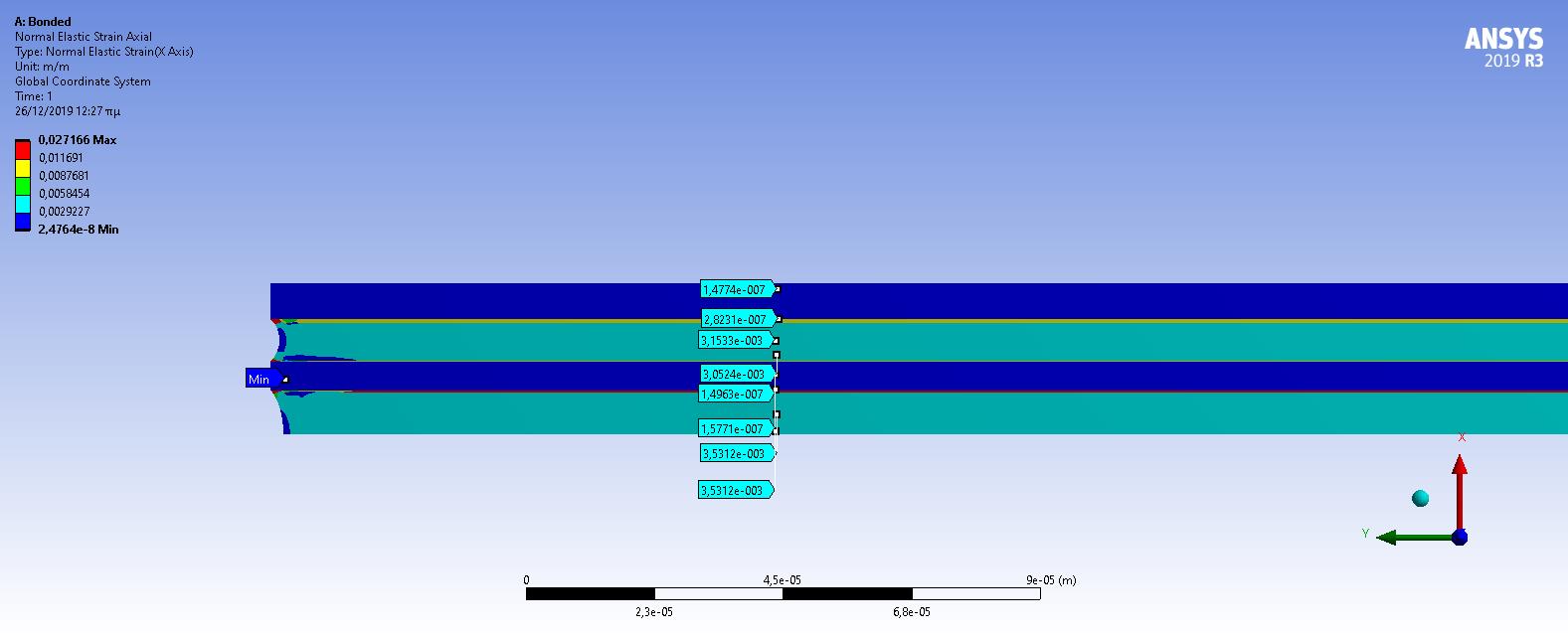
The problem is that on axil strains at the same y cordinate i have different strain result which is not true as my model is one compact body. Althought the directional deformation seems ok , if you increase the scale you will see that the left edge it doasent deform equal at its material domain thats the reason that i have different strains in the same y.
Thanks a lot.
-
December 25, 2019 at 10:26 pm
-
December 25, 2019 at 10:28 pm
-
December 25, 2019 at 11:02 pm
peteroznewman
SubscriberThe model is working just fine. Why are you looking at X-axis Strain? Don't do that.
Did you notice that when the cylinders are not bonded, the Strain is zero?
The relevant quantity is Y-axis displacement.
Don't pay attention to the last few microns of the length of the sample.
Pay attention to the uniform Y-displacement of the combined material as shown by the purple color. -
December 25, 2019 at 11:32 pm
Jmc79
SubscriberI want to have the strains in the y direction because my purpose is to add them to the strains results of a tensile pressure at the other edge of the model. so for steps from 20 to 30 c, 20 to 40 c , 20 to 50c .......20 to 100c i will have the resultan strains so i could check the small deviation of young modulus due to thermal load with my theoritical calculations and experimental data on my project.
If i dont have a fix result on a y coordinate i cant do that.
As i had tell you before if i put one body with the r7 diameter and give combine material properties from the percentance of each stand alone material (fiber,interface,matrix) i have good results.
-
December 25, 2019 at 11:33 pm
-
December 25, 2019 at 11:44 pm
peteroznewman
SubscriberWhat is the combined material properties? Once you assign a uniform material over the whole body, the strain will be zero.
-
December 25, 2019 at 11:56 pm
Jmc79
SubscriberIt’s not zero because I have fix constrain in one side and expansion of the model due to rising of temp.
In materials at structural you can create a combine material using other ones using exactly percent of any material you want.
For example
40%fiber
56%matrix
4% interface
As a result you have a combine material in one body -
December 26, 2019 at 3:44 am
peteroznewman
SubscriberThe model I made has no constraint, if you assign a uniform material, the strain is zero.
Which side are you constraining, the axial end or the radial side? Why don't you add that to the model?
-
February 19, 2020 at 7:44 pm
feifeishen
SubscriberHi, I have a thermal stress simulation problem regarding to the composite cylinder (triple layer tube). Do you have time to have a look?
Thanks
/forum/forums/topic/thermal-stress-for-multilayer-structure/
-
- The topic ‘Cylinder composite material model’ is closed to new replies.


-
2984
-
970
-
857
-
761
-
599

© 2025 Copyright ANSYS, Inc. All rights reserved.


