-
-
December 13, 2024 at 9:23 am
valerym.m5
SubscriberGood day,
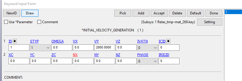
I have encountered many times a situation that is incomprehensible to me, setting the initial speed:
setting the speed direction (-/+) is interpreted in the program UNPREDICTABLY.
in particular, in the attached file the speed is set with the "+" sign - i.e. the direction is up,
but the body = to which the speed is applied - moves down, as I needmaybe I am making mistakes somewhere... or using the program settings incorrectly?
https://drive.google.com/file/d/1UgAJFev6nbMneTF-GcsvzFqwRH2cFDL6/view?usp=sharing -
December 16, 2024 at 8:06 pm
Pedram Samadian
Ansys EmployeeHi Valerym,
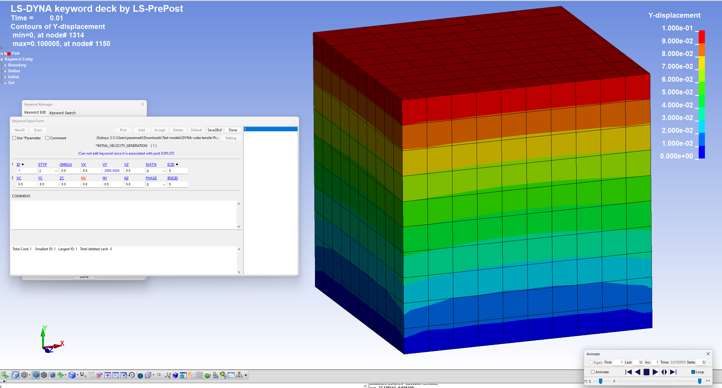
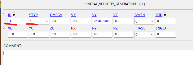
I created a simple cube tensile model and applied the same keyword card to define an initial velocity. As can be seen below, the displacements are positive as expected given the positive y-velocity provided. STYP in my model is 2 (i.e part ID) but is 1 in your model (i.e. part set ID). Make sure that your "part set #1" only includes the part you want to apply the initial velocity, not any other parts.
Thanks,
Pedram
-
December 18, 2024 at 12:49 pm
valerym.m5
SubscriberDear Pedram,
Thank you for your advice.
I checked the correctness of the initial velocity assignment in my model - everything is set correctly there.It was not by chance that I applied the term "unpredictable" to the assignment of the initial velocity for a rigid body.
I have already had several cases when the model correctly perceives the direction of the initial velocity, but then - in the process of some changes in the model, the specified direction of the initial velocity is perceived by LS-DYNA as the opposite, although I did not redefine the direction of the initial velocity.
*** Unfortunately, I have never been able to "fix" - at what stage of the model change LS-DYNA stops correctly perceiving the specified direction of the initial velocity.
As for your advice - to set the initial velocity for a specific part of the model - I will try to do this now and will write to you about the results.
Regards Valery
-
December 18, 2024 at 2:52 pm
valerym.m5
SubscriberDear Pedram,
I followed your advice – I set the initial speed for a specific part.
the model can be obtained from the specified link:
https://drive.google.com/file/d/1qKZq45Eu8MOuKVOMhO2-eEMXLpvbiQLV/view?usp=drive_link
to my regret, LS-DYNA perceives the set initial speed incorrectly:
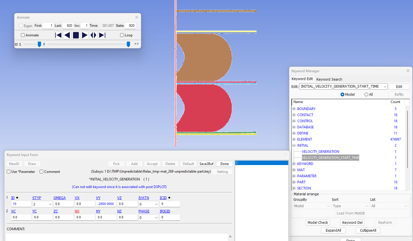
initial speed = – 2800 mm per second, direction down.but as you can see the part moves up.
-
December 18, 2024 at 3:13 pm
Pedram Samadian
Ansys EmployeeHi,
Thanks for the details. I am not sure which part the initial velocity was assigned to, but my guess is one part is hitting the other part based on this given velocity, and after the collision, the colliding part changes its moving direction. If that is the case, the reason you do not see the transfer of you part along the expected orientation before the collision might be the low output interval you set. Ensure your output interval in the DATABASE keyword cards is high enough to increase the resolution of the results (more data along the time).
Please keep me posted.
Thanks,
Pedram
-
December 18, 2024 at 3:49 pm
-
December 18, 2024 at 3:51 pm
Pedram Samadian
Ansys EmployeeHow long does it take for the part with velocity to reach the stationary part?
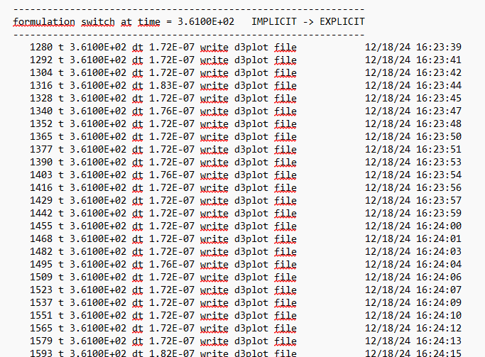
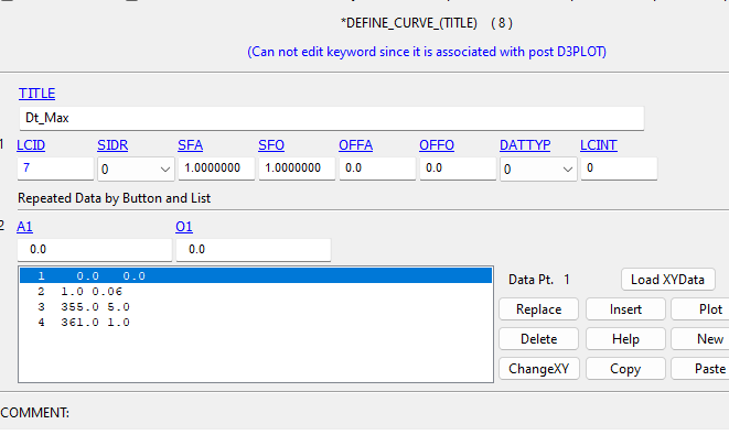
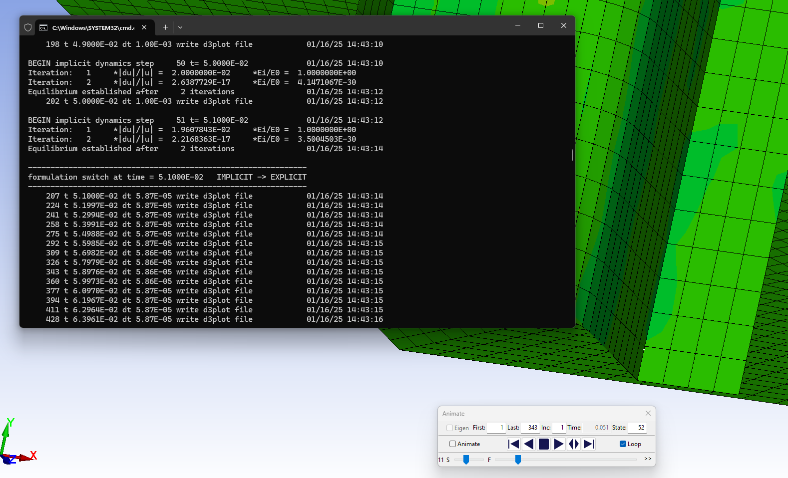
I also see the time-integration scheme has changed from implicit to explicit at some point. The implicit time steps are much higher than the explicit ones. What was the time step size for the implicit portion of the simulation?
-
December 18, 2024 at 4:03 pm
valerym.m5
Subscriberthe gap between parts = 1.02 mm
initial speed 2800 mm per second
time it takes to start contact = 0.000364 seconds -
December 18, 2024 at 4:06 pm
-
-
December 18, 2024 at 3:55 pm
valerym.m5
Subscriberby the way, getting/writing calculation results according to the curve with sequential use of implicit and explicit solver is also a problem for me - which I wrote about here:
https://innovationspace.ansys.com/forum/forums/topic/restart-switch-implicit-gt-explicit/ -
January 8, 2025 at 4:23 pm
Pedram Samadian
Ansys EmployeeHi Valery,
Thanks for the details. Unfortunately, I cannot download your model here to figure out what is going on in your model unless you can send it through Ansys Customer Support Space (ACSS).
The contact is established after 0.000364 s, so please ensure that your output interval for d3plot (in *DATABASE_BINARY_D3PLOT) in the implicit portion of your simulation is lower than this. Then plot the velocity history of the part. The velocity sign must be consistent with the direction of the part movement in each output within the period of 0 s to 0.000364 s.
Thanks,
Pedram
-
January 9, 2025 at 8:59 am
valerym.m5
SubscriberDear Pedram,
I will definitely take advantage of your kind offer.But first I would like to make sure that my assumptions are correct.
So:
1. I could not learn to regulate the recording of calculation results at the initial stage of using an explicit solver.
For some unknown reason, the program ignores my instructions and writes the calculation results “arbitrarily” – immediately after switching the solver type – in this model – about 0.02 seconds.
After 0.02 seconds, the results are recorded with a step “close” to the required step, but still not exactly to my requirements specified in the curve.- I am interested in the calculation results at the initial moment of time – at the moment of impact of the load.
2. Since I couldn’t solve the 1st problem, I tried to use the command:
Velocity_Generation_Start_Time
Where, according to the documentation, you can set a “delay” in time for the initial velocity applied to the “rigid” body.
However, ls-dyna ignores any specified delay values and the initial velocity is activated at the moment of switching from the implicit to the explicit solver.3. Taking into account my unsuccessful attempts 1 and 2.
I decided to achieve the required delay in the time of application of the initial velocity by moving the falling load a distance that I calculated from the specified initial velocity of 1000 mm per second.
However, from the analysis of the solution I found that the initial velocity of the load is not 1000 mm per second, but 2567 mm per second!0.00805664 sec is the time of motion of the rigid body
20.68639946 mm is the distance the rigid body has moved
2567.62117458 mm/sec is the constant speed of motionIf someone wants to get acquainted with my model – see the link below
https://drive.google.com/file/d/1jf3XCB1v87ImHqMO-PfN6SXNVcTPGAUT/view?usp=sharing
I will be very grateful for any advice – since in this case I have a stalemate.
———————————-
I tried to solve this problem with other data – trying to understand possible patterns, and I was very surprised, since the initial speed given was different each time?!
Below is another example of the solution
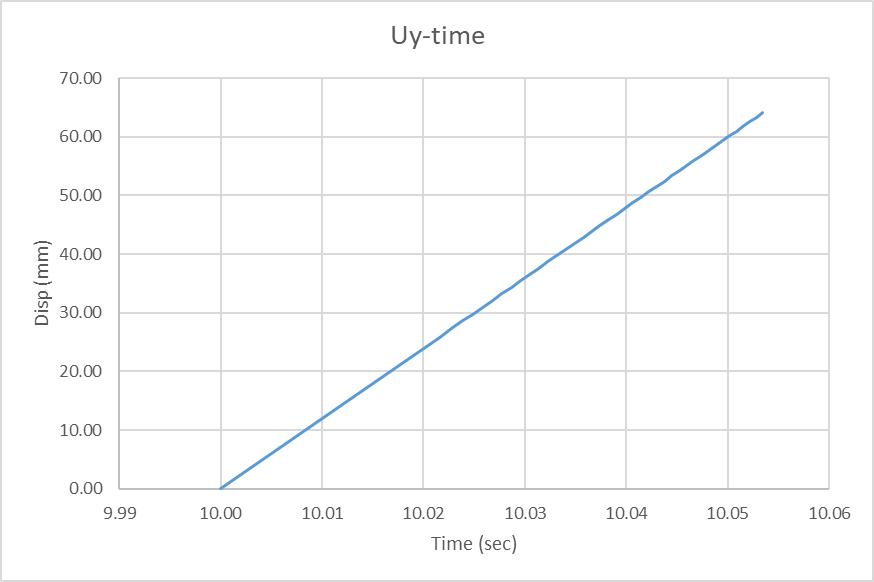
time Uy 10.0000000 0.0000000 10.0168285 20.1738129 10.0215492 25.8324966 10.0228729 27.4195175 10.0238628 28.6061802 10.0248413 29.7792721 10.0258083 30.9385910 10.0267649 32.0844803 10.0277100 33.2173271 10.0286436 34.3369370 10.0295668 35.4437866 10.0304794 36.5377007 10.0313816 37.6189613 10.0322733 38.6876526 10.0331545 39.7442780 10.0340252 40.7885284 10.0348864 41.8205681 10.0357380 42.8409538 10.0365791 43.8493919 10.0374107 44.8462029 10.0382328 45.8315926 10.0390453 46.8054848 10.0398483 47.7680931 10.0406418 48.7197609 10.0414267 49.6601524 10.0422020 50.5898819 10.0429688 51.5088005 10.0437260 52.4171677 10.0444756 53.3149796 10.0452156 54.2024994 10.0459471 55.0797882 10.0466709 55.9469223 10.0473852 56.8037834 10.0480919 57.6509781 10.0487909 58.4884300 10.0494814 59.3161201 10.0501642 60.1341667 10.0508385 60.9428711 10.0515051 61.7423515 10.0521641 62.5323830 10.0528164 63.3134384 10.0534601 64.0852509 Dt 0.0534601 D_Uy 64.0852509 speed 1198.7487 For the last solution, the initial speed was specified -2800 mm per second,
but in reality – according to the calculation – the speed was 1198 mm per second
-
January 9, 2025 at 10:52 am
valerym.m5
Subscriberhere is another fact - which I cannot understand:
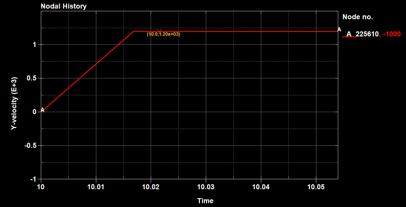
judging by the graph - the initial velocity of the rigid body increases over a fairly long period of time.I do not specify this period of time...
ls-dyan somehow determines it itself.....
Nothing is said about this in the documentation... - to be more precise, I did not find anything
hence the question:
and how then can one specify the initial velocity of the rigid body - without the "acceleration time"??
Is it possible to do this at all?
and one more question:
I specify the initial velocity of 1000 mm per second, and here again ls-dyan "acts up"... - the velocity - judging by the graph:
1.1987445068e+03 mm per second
1.0016828537e+01 1.1987445068e+03
-
January 9, 2025 at 11:05 am
valerym.m5
Subscriberin my model, the parameter PHASE:=0
EQ.0. Velocities applied immediately
but if I understand the calculation results correctly, then ls-dyna solves the problem with the parameter PHASE:=0 EQ.1. Velocities applied after dynamic relaxation.
and with this ls-dyna somehow independently calculates the period of dynamic relaxation and for some reason it also changes the amplitude/magnitude of the initial velocity that I set. -
January 9, 2025 at 8:21 pm
Pedram Samadian
Ansys EmployeeHi Valery,
Can you please show your specified output interval histroy that includes both the implicit and explicit parts of your model? The image in your 4th comment shows that as the solver changes from implicit to explicit, an output is written in the d3plot. Where is that 0.02 second gap?
The *LSO_TIME_SEQUENCE card may also help you for managing output writing (LS-DYNA Multiphysics Manual).
Using Velocity_Generation_Start_Time, the initial velocity occurs only in the regular transient phase after dynamic relaxation (if used). Neither PHASE value will cause initial velocity to be imposed in the dynamic relaxation phase. It is surprising that the velocity does not start from what you specified, but given the previous explanation, maybe dynamic relation is being applied during that period.
Please also make sure to use the lastest LS-DYNA solver downloadable at LS-DYNA (user=user) Download Page(username: user & password: computer). The double precision type is recommended.
I hope this information helps you.
Pedram
-
January 11, 2025 at 2:18 pm
valerym.m5
SubscriberGood day Pedra
thank you for your recommendations.
As for the curves concerning the maximum value of the integration step and the step of output of the calculation results – they are in the model.
But as far as I understand, if the model uses switching from an implicit to an explicit solver,
then in this case – ls-dyna does not want to fulfill the exact requirements for output of the calculation results specified in the curve.it not only writes the results “arbitrarily”, but also changes the “prescribed” value of the initial velocity – as a rule, to a greater one.
maybe I’m wrong about something – since my experience with ls-dyna is very modest.
So I hope to hear the opinion of more qualified engineers.
Reagrds Valery
-
-
January 11, 2025 at 12:23 pm
valerym.m5
SubscriberDear colleagues,
I offer you two models that demonstrate “oddities” that I could not understand.
I will be glad if you write your assumptions… advice…. comments…
====================
Model
STYP-2_Relax.key
Link to the model:
https://drive.google.com/file/d/1P3C9CnTEGN145BxeU_X8ALUofHXnlTHp/view?usp=sharingThe initial speed of the cargo is set: -1000 mm per second
The cargo moves down.
As the calculation results show, the load receives a real initial speed in the calculation: -2594.6645508 mm per second
during the rise time: 0.00009155 sec – see belowVy.txt
3.6099996948e+02 0.0000000000e+00
3.6100009155e+02 -2.5946645508e+03
3.6100531006e+02 -2.5946645508e+03======================
Model
No_Relax_1.222e-4-1000mm_0_023sec.key
link to the model :
https://drive.google.com/file/d/1eOWIbv6e2wMkJ7HqZMFYVccMiwD1LyFJ/view?usp=sharingThe initial velocity of the cargo is set: -1000 mm per second
The cargo moves up.
Curveplot
Nodal History
Time
Y-velocity
Node no.
222980 #pts=266
* Minval= -1.0000000000e+03 at time= 0.0000000000
* Maxval= 3.7985620117e+03 at time= 10.0000991821
9.9999990463e+00 0.0000000000e+00
1.0000099182e+01 3.7985620117e+03
1.0001098633e+01 3.7985620117e+03========================================
List of questions I wanted to would like to get answers:
1. why, when setting one “initial” speed – 1000 mm per second,
in the first model – the cargo moves down, and in the second model – the cargo moves up?2. why, when setting one “initial” speed – 1000 mm per second,
in the first model – the actual speed of the cargo according to calculations = - (MINUS) 2594.6645508 mm per second,
and in the second model – the actual speed of the cargo according to calculations = + (PLUS) 3798.5620117 mm per second?3. Why do the above “initial” speeds reach constant values in different times?
-
January 11, 2025 at 12:47 pm
valerym.m5
Subscriberby the way, here is another model where the initial speed is given with a plus sign:
+1000 mm per secondhttps://drive.google.com/file/d/1xZ0Byw0l9EbzeD-TFVCRAJDfirI0DbcJ/view?usp=sharing
but in fact, according to calculations - the speed is NEGATIVE = - 1117 mm per second
9.9497890472e+00 0.0000000000e+00
1.0000000000e+01 0.0000000000e+00
1.0008694649e+01 -1.1772938232e+03
1.0009955406e+01 -1.1772938232e+03i.e. a body with a given positive speed = +1000 mm per second should move up, but for some reason the body moves down?!
-
January 15, 2025 at 3:47 pm
Pedram Samadian
Ansys EmployeeHi Valery,
Please remove any relevant mass scaling and dynamic relaxation cards (e.g. control_timestep and control_dynamic_relaxation) from the model and then run it.
Please keep me posted on the outcome.
Thanks,
Pedram
-
January 16, 2025 at 1:26 pm
valerym.m5
SubscriberHi Pedram,
unfortunately, removing the mentioned cards did not produce any positive results.
Regards Valery
-
-
January 15, 2025 at 7:18 pm
valerym.m5
SubscriberHi Pedram,
thank you very much for your advice – I will try to use your advice.
However, I hope to get answers to my questions from more qualified colleagues.
I find it hard to believe that no one has tried to solve such problems before and tried to figure out what is going on?To my regret, I could not find even a brief description of the "actions" of the program
when switching solvers (implicit <=> explicit) occurs using a curve.Maybe someone has already found at least some information on this issue?
Regards Valery -
January 16, 2025 at 8:20 pm
Pedram Samadian
Ansys EmployeeHi Valery,
I am sorry that the issue is still persisting. Unfortunately, I cannot reproduce the error you are getting in simple models I created. In my last try, I built a simple impact model and used the initial velicity generation card and a combined implicit-explicit time integration scheme (implicit before collision and explicit after that). In the predictions, the part moved in the same direction as that specified in the initial velicity generation card until the collision and could get recordings at the preset time intervals, including the exact time when the explicit solver starts working (you can see it in the image below).
We need to review your model in detail to see what the problem is. As I noted, Ansys employees cannot download or upload files on the Forum platform, but it can be done through Ansys Customer Support Space (ACSS) after users open a ticket.
Thanks,
Pedram -
January 23, 2025 at 10:15 am
valerym.m5
SubscriberDear Pergam,
probably I did not explain the problems clearly enough.
The issue is not that the solvers would switch at the required time.
I will briefly list the main problems again
1. the start time of the initial velocity application specified in the map “Velocity_Generation_Start_Time” is ignored
2. ls-dyan arbitrarily changes the value of the specified initial velocity, when using the technology of switching solvers during the solution of the problem.
for example – the initial velocity is set to – (minus) 1000, and from the analysis of the obtained solution – the real initial velocity is – (minus) 2594!
Moreover, there were cases when – the initial velocity is set to – (minus) 1000, and from the analysis of the obtained solution – the real initial velocity is + (PLUS) 2594!
3. Completely incomprehensible cases occur, for example:
as a result of setting a negative value of the initial velocity, the body should move downwards, but in some cases – it starts moving upwards!There were other cases (numerous) – when a positive initial velocity was set, and the body began to move downwards!
Regards Valery -
January 23, 2025 at 4:33 pm
valerym.m5
Subscriberhere is another "incomprehensible" example:
https://drive.google.com/file/d/1wkfTCIeIb8E_D7I4P8pYGQTSjuPKUWTd/view?usp=sharingfirst option - initial velocity is set to - (minus) 992 mm/sec
real initial velocity during solution analysis is -2331 mm/secas it should be - the body moves down
second option - initial velocity is set to - (minus) 1102 mm/sec
real initial velocity during solution analysis is + (plus) 2717 2.7169147949e+03 mm/secthe body moves up!!
the model is used without any changes!
only the initial velocity changes!
-
January 28, 2025 at 8:15 am
valerym.m5
Subscriberanother "strange" situation:
below is a link to the model
https://drive.google.com/file/d/1X9HhXJ6nybtnQQrRoOcq9eNykMJVEnBf/view?usp=sharinginitially, this model used an elastic material for steel plates.
the initial speed was set to 1075 mm per second,
the real initial speed - with which the problem was solved was 2571 mm per second.
Ok!
it is already good that the displacement corresponds to the sign of the speedbut when I added the elastic-plastic material MAT_03 to this model - the load began to move up, not down!!!
nothing changed except the new model MAT_03 introduced.
it would be very useful to hear hypotheses regarding the question:
How can a new material change the direction of movement?
Maybe I don't understand something? -
February 14, 2025 at 8:28 pm
Pedram Samadian
Ansys EmployeeHi Valery,
I encountered a reported bug for the initia velocity generation keyword that might have been making a problem for your model. If my guess is correct, changing the set type in the card (STYP) to a node set should fix the issue.
I look forward to your feedback.
Thanks,
Pedram
-
February 15, 2025 at 1:18 pm
valerym.m5
SubscriberDear Pedram,
previously, I experimented with the card (STYP) many times.
Unfortunately, I never got a positive result.
Probably, the reasons for "complete uncontrollability" when setting the initial speed with an offset are much more serious.
Regards Valery -
February 19, 2025 at 4:03 pm
Pedram Samadian
Ansys EmployeeHi Valery,
Thanks for the feedback. Another workaround is to use the R16 solver, which should be released in coming days. The bug in the Initial Velocity Generation card has been fixed in this solver.
Cheers,
Pedram
-
February 19, 2025 at 5:46 pm
-
February 19, 2025 at 8:58 pm
Pedram Samadian
Ansys EmployeeHi Valery,
Any bugs reported for different keywords should be fixed in the new solver. Try the new solver when it is released, and then give us feedback, please.
Thanks,
Pedram
-
- You must be logged in to reply to this topic.


-
4633
-
1535
-
1386
-
1225
-
1021

© 2025 Copyright ANSYS, Inc. All rights reserved.

