Ansys Products

Ansys Products

Discuss installation & licensing of our Ansys Teaching and Research products.

#need help. i find its difficult to create model of steel box girder.

TAGGED: 

    • abc164
      Subscriber

      i am a engineer. i use ansys to simulate steel box girder. find it hard to create the model. be more specific, its hard to connect plates of different direction. basically, there are two groups of plates. ones is the main plates, which also be called longitudinal plates. other one is lateral plates. i use AGLUE/AOVLAP command to connect longitudinal plates or lateral plates. and it works fine. BUT , when the command try to connect longitudinal plates and lateral plates, errors occur. "The input areas do not meet the conditions required for the AOVL operation... ". so i have to use CE command to connect them. any other good solution to connect them? i dont want to use CE. thank you.

      longitudinal plates:

       lateral plates:

      together:

    • Ashish Khemka
      Forum Moderator

      Hi,

      You can try using the command: NUMMRG,KP

      If two separate entities have the same location, you can merge these entities together into a single entity via the NUMMRG command. The NUMMRG command does not changes model geometry. Only the topology is affected.

      10.1. Number Control

      NUMMRG

      Regards,

      Ashish Khemka


    • abc164
      Subscriber

      nummrg merge coincident entities. it can link lines which share coincident points. this order is effective when the situation A, but not effective in the situation B. and mine belongs to the situation B.

      situation A


      situation B


    • Ashish Khemka
      Forum Moderator

      Hello,

      Do you have nodes at the above locations in Situation B? If yes, then you can use NUMMRG for nodes.

      Regards,

      Ashish Khemka

    • abc164
      Subscriber

      nodes are generated by amesh order. i cannot control the exact location of nodes. at most situations, node will not be generated at the the intersect point of these lines. to fix it,wo have to make extra keypoint in the intersection points in the above line, which means transferring situation B to situation A. but doing this increase labor cost. any good solutions?

    • wrbulat
      Ansys Employee

      You may need to subdivide areas with the workplane (ASBW) in such a way that an AGLUE command will result in shared topology.

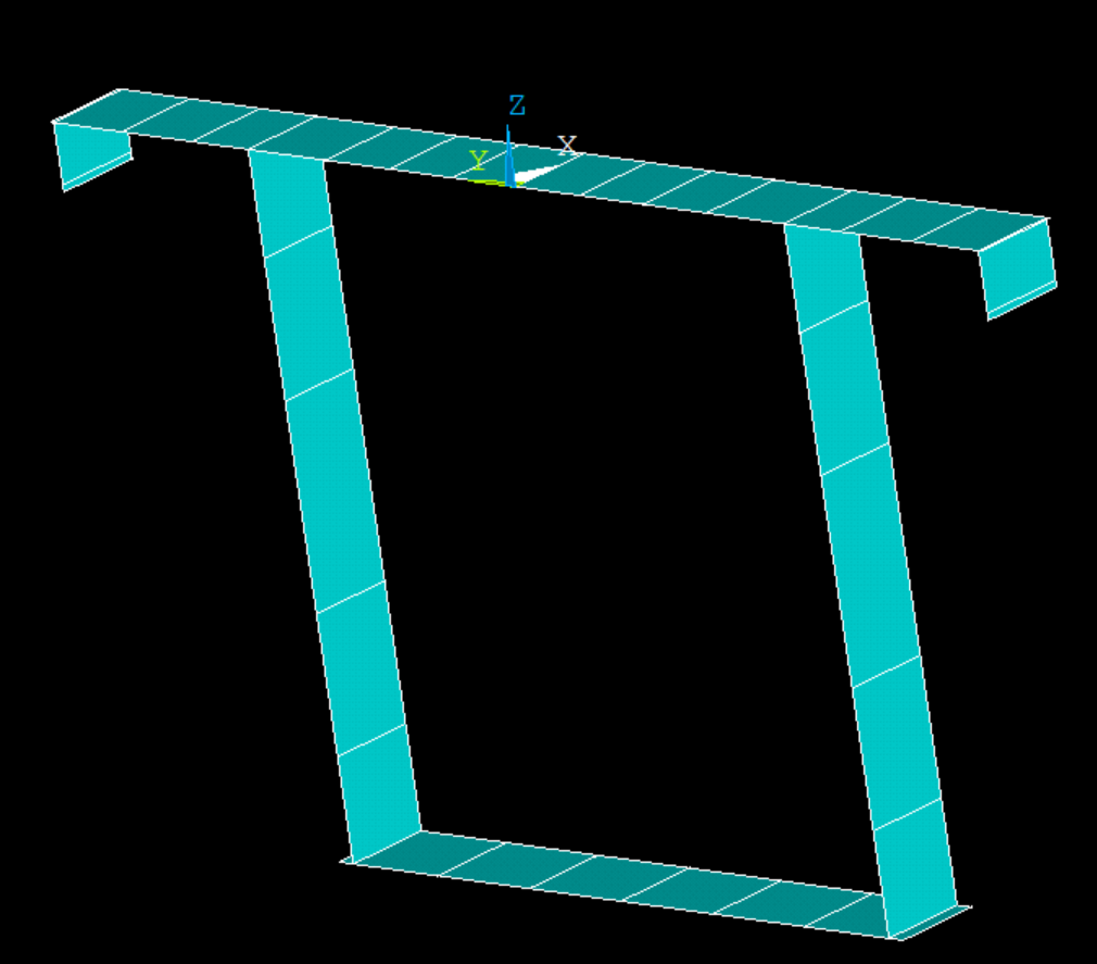
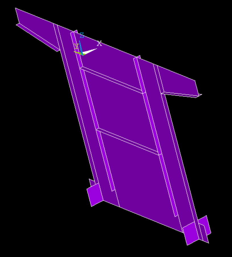
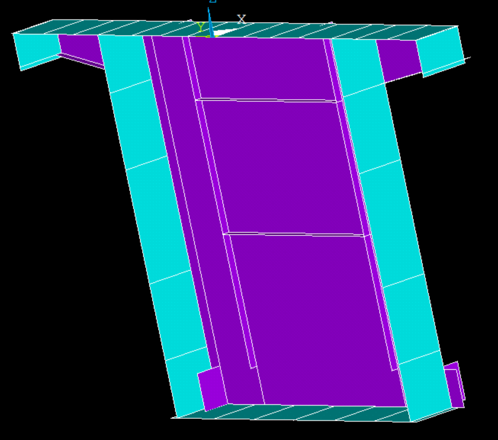
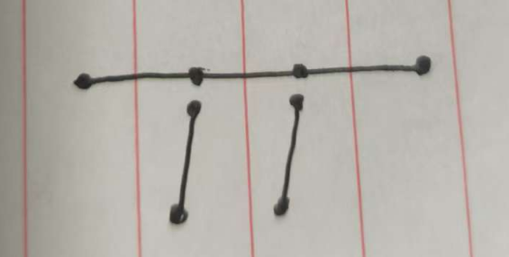
      For example, I would expect problems with the geometry circled in red in the image below.

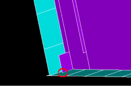
      The vertex of the purple area ends in the middle of the blue one - I can't imagine any of the MAPDL boolean operators would be able to deal with this sucessfully.

      If you can position/orient the workplane (e.g., KWPA, WPRO) then use it to slice the blue area into two areas (ASBW), resulting in an edge that is colinear with the one on the purple area (red line in image below):

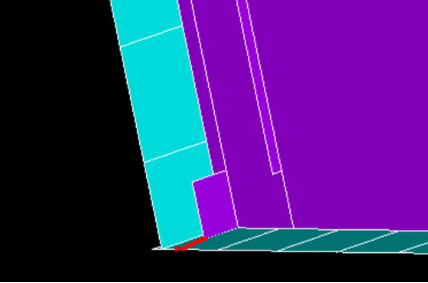
      I think that might allow you to glue the areas with AGLU.

      If successful, this will of course result in shared topology between the areas and shared nodes on the interface between them after meshing, which appears to be your objective.

      You may need to modify other similar locations in the geometry wherever they exist using graphical picking (e.g., ASBW,P) and glue individually picked areas (subsets of all the areas) with AGLUE,P. As-is, your geometry does not appear to be amenable to a "blanket" operation performed on all the areas at once (e.g., AGLUE,ALL). Likely some manual interactive geometry modification will be needed.

      If you want this subdivision process to be automated (say, by a macro that you call after importing geometry) it might be possible to devise APDL that automatically identifies conditions such as the one shown in the first image above and performs the subdivision for you, but that would require some thought, testing, and effort.

      --Bill


    • abc164
      Subscriber

      thanks. i think i got your point. AGLUE is valid after amend the model. actually ,the longitudinal plates and lateral plates showing in the first two pictures are created by automated script. these plates are nearly up to 1000. i have no idea to make they share nodes at their boundary.  at current, the script is half-automated.that is why i am hear to get some idea to do so.

Viewing 6 reply threads
  • You must be logged in to reply to this topic.