-
-
December 5, 2024 at 7:56 pm
arezoo.tahmasebi
SubscriberDear colleagues,
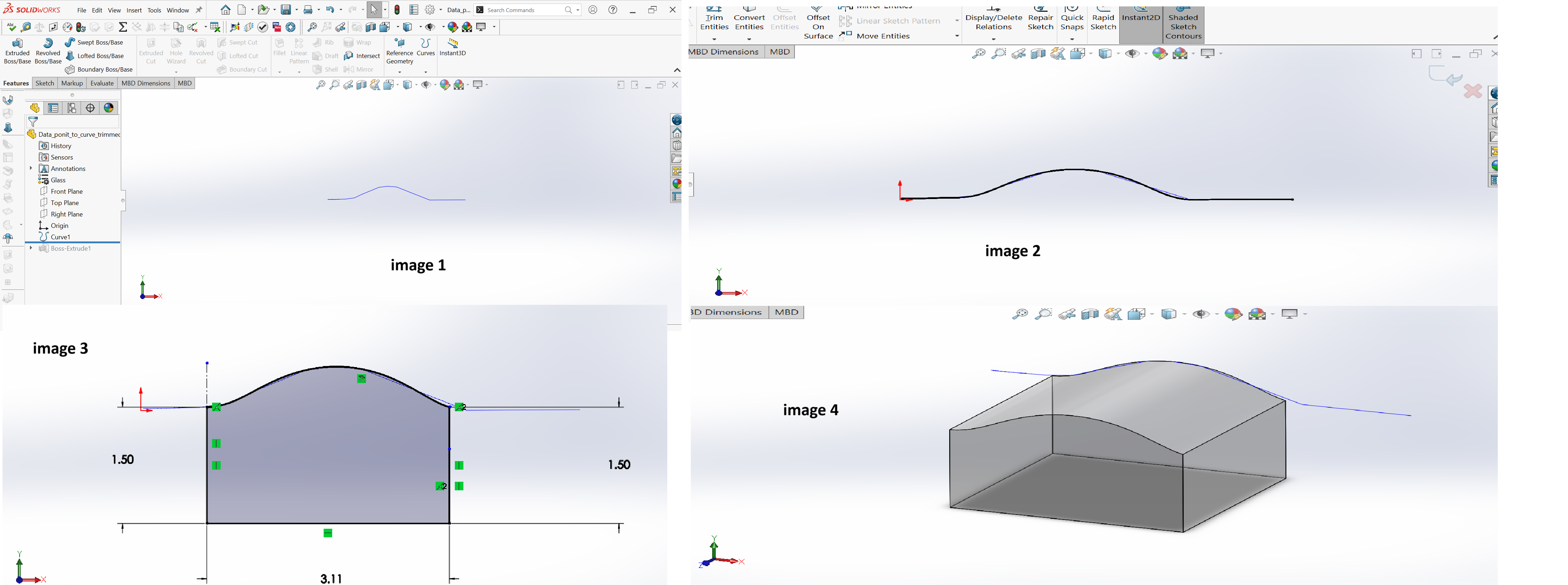
I've got a data point for a curve. I used the command Curve through XYZ points in Solidworks to draw the curve (see image 1).
Next, I converted the curve to a representative sketch using the command Convert entities in SolidWorks (Image 2). Then I drew some lines to make the sketch a closed one (Image 3) and extruded it to make it a solid body (Image 4).
The issue is that when I add the step file for this body to Zemax, as soon as I place it in front of the source, I get a 'Geometry error. Run the NSC ray tracing for more info' message.
Any ideas?
-
December 9, 2024 at 10:50 am
Niki Papachristou
Forum ModeratorHi Arezoo,
Thank you for reaching out to us! Tou can find detailed information on Geometry errors in these two Knowledge base articles:
How to locate geometry errors: part I
How to locate geometry errors part II - design examples
However if your question is not covered there feel free to let me know.
Kind Regards,
Niki
-
- You must be logged in to reply to this topic.


-
4838
-
1587
-
1386
-
1242
-
1021

© 2026 Copyright ANSYS, Inc. All rights reserved.


